1. Fields & Definitions for BOM & AVL

1.1. Bill Of Material Main Screen

This is the screen that appears when opening the module. The product number is displayed in the Bill of Material Module screen header as a reference.  The product information will remain on screen while viewing other sections of the BOM module.  BOM Main may be used to view, edit, add or delete a Bill of Material.  BOM Header information is displayed for any item located after a FIND.  If any Line Items have been added to an assembly in the BOM Header, they will be displayed in the Detail Window below.  The lines that are inactive will be highlighted in purple. Selection of a Line Item in the Detail Window will cause the other BOM screens to be populated with default and/or added information for that Line Item. Start with this screen to add a new BOM, edit an existing BOM, add a new Line Item or change detail information for existing Line Items.                

The Header Information fields across the upper half of the screen are populated from the item master and from keyed-in assembly data. The fields in the Body (Detail Window) show information about the components included in the assembly.

BOM Main Field Definitions

Class

The Part Class assigned to the assembly in the Item Master.

Type

The Part Type assigned to the assembly in the Item Master.

Description

The Item Master description for the Assembly Part.

Product

The Part Number for the assembly. Can be the customers product no. or an auto-assigned internal Part Number.

Rev

The Part Number Revision for the assembly. An assembly may exist under multiple revisions.A separate BOM is required for each.

Matl Type This is defaulted in from Inventory Control

Any notes pertaining to the BOM will display upon depress the Note button.

 
Depressing the down arrow will display the history of the BOM components. Current reflects the most recent listing; BOM History will display the history of changes. Selected Date will bring up a selection screen.
 
Note:  If the effectivity and obsolete dates are used, then it is possible to check the specific parts list at any given data using the BOM history. 
 

Status
The BOM Status:  Active - BOM is Active; 
Inactive - BOM is Inactive which will affect Cost Roll up.   NOTE:  Changing the BOM status to Inactive will NOT remove the MRP demands you MUST Inactivate the part number in ICM to remove the MRP demands.  See Article #3430 for further detail.
Quote
-  This status is in case a BOM is in a quote stage and the user needs a reminder that the quote for this BOM is pending.   
 
This status is for the BOM ONLY, it will NOT change the status of the Inventory part.  The Inventory part status and BOM status can be different.  This is to allow flexibility so the BOM can be inactive and will NOT be displayed in the BOM module, but the part will still be displayed in the inventory listing.   Users will be allowed to change the status on a BOM from Active to Inactive with open SO, WO, etc. and MRP will still show demands.  Users will also still be allowed to Create NEW SO, WO, etc if ONLY the BOM status is Inactive.  Users will NOT be allowed to change the status on the Inventory part from Active to Inactive with open SO, WO, etc. 
When the BOM is made Inactive this field will display the status along with the date and Initials of the user that Inactivated the BOM.
This allows the user to find part by Reference Designator.  If user starts typing reference designator into the text box it will auto fill the information, when done entering user can press "Enter" or click on the search button next to it and the record pointer in the grid will advance to the part if a match is found.

Customer Name

The name of the customer for whom the user is making the assembly.Select from pull-down list. Add new customers in Customer Information Management. Use Standard Pricing as the customer or leave blank if the assembly is built to stock or has more than one potential customer. This field must match the Customer for any Consigned parts used in the BOM.

Setup Stscp

This box MUST be checked if you wish for the setup scrap qty’s to be included in the Kitting and MRP calculations,  Checking this box along with a Standard Bld qty will tell the system to use Setup Scrap when calculating the standard cost.   Note:  The "Exclude Scrap & Setup Scrap" options within the  Kitting Setup module will overwrite this option. 

Standard Bld

The quantity normally built. Entering a quantity in this box will be used when calculating the Standard Cost.  See Article 3040 for information on how this affects the Std Cost.  See Articles #3067 , #3053 , and #3320 for information on how this affects the Configuration Variance.
Last Change

The date and time of the last change to the BOM automatically enters this field.

By Initials of user that made last change to BOM.
Mgmt Lock
This option is for BOM's that need to be protected, even from those users that have edit capabilities.  Only Supervisors or users with Lock/Unlock rights within the Security/User rights can modify this checkbox.   If locked, all users can access the screen,  but only supervisors or those with Lock/Unlock rights will have the capability to bypass the lock and make changes, while the BOM is still in lock mode.  The reason we do NOT force the user to unlock the BOM before making any changes, is to protect it from anyone else making changes while the  'authorized" user is making their changes.     
Lock Date The date the Managment Lock Box was checked.
By The initials of the user that check the Managment Lock Box.

COMPONENT INFORMATION (Displayed in the Body (Detail Window)

Item

The item numbers assigned to the components in the BOM.

Part Source

The sources of the assembly components.Select Make, Buy, Consigned or Phantom.

Part Number/Rev

The components internal Manex part number. The Part Number Revision for the component. A component may exist under multiple revisions. Each Rev. is considered a unique part number and may co-exist with other Revs. or replace other Revs.

Customer Part Number/Rev
 

The component's customer part number. The Part Number Revision for the component. A component may exist under multiple revisions. Each Rev. is considered a unique part number and may co-exist with other Revs. or replace other Revs.

Class

The Part Class of the component part as assigned in the Item Master.

Type

The Part Type of the component part as assigned in the Item Master.

Description

The Item Master description of the component part.

Quantity

The quantity of the component part used in the assembly.Do not add to the quantity field to compensate for setup and run losses; Use the Setup % and Run Qty. fields in the Item Master screen to add components to cover production losses.

Column Heading in Bold Font

These columns, when selected will cause the Detail information below them to be sorted by the field selected.  Selected Column headers turn Red.


1.2. Item Detail Information Tab

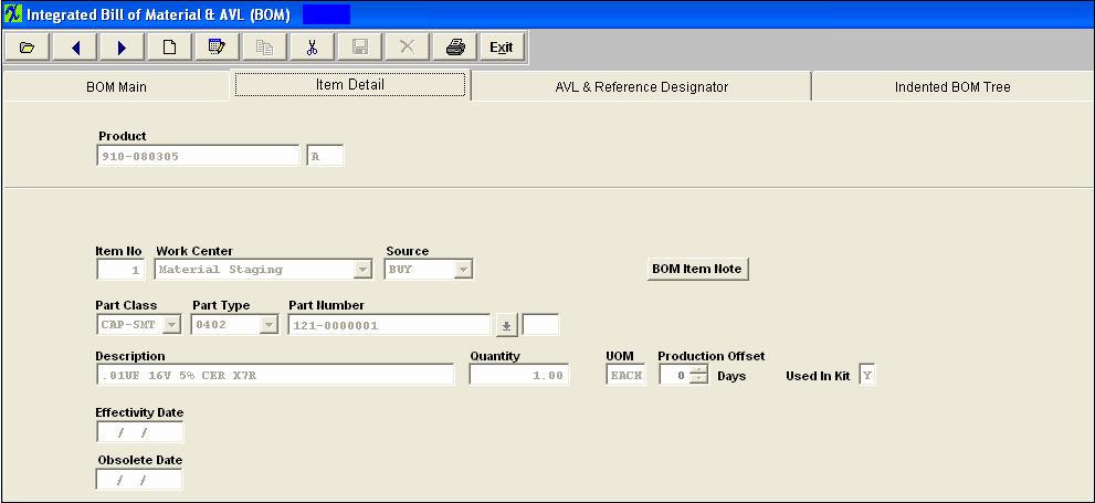
When the user has displayed component parts on the BOM Main screen, and has highlighted one of the parts, pressing on the Item Detail Tab will display information about

that component part.  The NEXT and PRIOR buttons are activated in the Detail Information Tabs. Clicking on either button will display the details of the next component in the BOM.


The first row of Header information repeats the assembly Product information.


The remaining fields describe Detail information about the component part.


Item Detail Screen Fields  


HEADER INFORMATION 


 Product The Part Number of the assembly.  Make Items are referred to as Products.
 Rev   The Revision of the assembly number, phantom or subassembly.


 COMPONENT INFORMATION


Item No         The item number assigned to the components in the BOM.
Work Center        The work center identified in the routing for the assembly at which the part is needed. Kitting of the part by work center will use this information to determine which parts are to be kitted for each work center.
Source    
The Source Code for the component part on the BOM. May be another MAKE assembly, a PHANTOM assembly, a BUY part, or a CONSIGNED part. 

When building a BOM in order to have the Source "CONSIGNED" displayed a Customer MUST be assigned to the BOM.  


When building a BOM and you enter the source as a “Phantom”, then when entering the part number that is a “Make/Phantom”, the source changes to a Make” part.   The reason the source field shows at all is to limit the number of part numbers that are available to choose from.   But you can enter any valid part number and the source will change to the source of the part number entered.  So, yes, the source of the sub-assemblies will show as a “Make” part, even though they are actually “Make/Phantom” parts. The details of the BOM will also show they are “Make/Phantoms”.   We allow nested phantoms, of either the “PHANTOM” or the “Make/Phantom” variety.  In kitting, we have the code to blow down through the first level of make/phantoms, so that the parts included in the first sub-assembly level down are listed as kit requirements. We have extended this further so that if there are Make/Phantom parts in the first sub-assembly level, those also break down to the components in the second sub-assembly level.  This process extends as long as there are “Make/Phantoms” in the indented BOM.

Part Class  The Part Class of the component part.
Part Type The Part Type of the component part.
Part Number    The component part number.
Rev    The Revision number of the component.
Customer Part Number The number the customer uses to identify the part.
Rev   The Revision number of the customer’s component.
Description  The description of the component part.
Quantity    The quantity of the component part used in the assembly.  The maximum number of decimals in the BOM quantity is 2, allowing for 1/100th of an item.  If users need a finer resolution, they may consider using a different UoM than EACH, and buy in one unit and use a fractional unit for inventory (e.g. Purchase in Gallons, and Stock/Issue in ounces).
UOM   The stocking/kitting unit of measure for the part.
Production Offset  
Production offset is a BoM item level field that allows users to control delivery dates in relation to the starting date of the work order.  By using this field, the user may move the material requirement date by the specified number of days in either direction.   Enter the number of days after the start date (based on the production lead-time for the assembly) that the part is needed at the kit-to Work Center.   NOTE: This will affect the MRP demands until the kit status has been changed to "KIT IN PROCESS".   Once the kit status has been changed to "Kit in Process" the parts now become a kit shortage, and  the system will calculate from the WO due date or production lead time and NOT from the production offset. .   A Negative Offset is one that SUBTRACTS time from the normal kit required date. So an item normally due on March 26 would, with a -3 day offset, be due in the stockroom on March 21st . Conversely, a Positive Offset is one that ADDS time to the normal kitting time.  So an item normally due on March 26 would, with a 3 day offset, be due in the stockroom on March 29th  (skipping the weekend).  Offsets are only managed by days, so there would never be a 3 week or 2 month offset, only 21 days or 60 days.
Used in Kit  "Y", "N", or "F" - Identifies the part if requires kitting from the storeroom.  Typical Non-kitted items include chemicals and adhesives that are re-issued when they run low but are included on the BOM for costing or reference.  Note:  A non-kitted item will create MRP demands.  For more information see Article #34.
Effectivity Date   
This is the date that the part is added and/or removed from the BOM and the demands will be displayed in MRPMRP picks up all the records with an effective date earlier or equal to current date, and all NULL/BLANK effective dates.    If the user changes parts in the BOM, without changing the revision of the BOM, then they should be entering the effectivity date of the new part, and the obsolete date of the old part.  Usually, they are the same date for a replacement item.  It is the date that is used in the determination of what material is to be used in kitting.  If the kit is due to ship before the date(s), then the old definition will apply.  If the kit is due to ship after the date(s), then the new definition will apply when the kit is updated.  When printing BOMs, the information included will depend on the selection they want to see.  Current will display whatever is effective on today’s date.  History will display ALL items.  Selected date will display the BOM as of the date entered.  The old items will continue to show up on a where-used report.  This is a good thing, because when you are trying to figure out where all of the old obsolete inventory came from, you can trace it back to the assembly and customer. 

Note:  The Kitted BOM Cost calculations displayed on the "Kit to Close Report" is based off the WO Due date and compares that to the EFF/OB dates on the BOM.  So users need to be VERY careful with the WO Due Dates and make sure that they stay current along with the EFF/OB dates on the BOM.   
Obsolete Date   
The date the part is no longer required on the BOM for new work orders and the demands will NOT be displayed in MRP.   

Note:
  The Kitted BOM Cost calculations displayed on the "Kit to Close Report" is based off the WO Due date and compares that to the EFF/OB dates on the BOM.  So users need to be VERY careful with the WO Due Dates and make sure that they stay current along with the EFF/OB dates on the BOM.   


DIRECTIVE BUTTON


The following button is displayed on the BOM Item Detail screen:


  Pressing the BOM Item Note button will allow the user to create a notation specific to the component shown, in the current BOM.  To enter a note, depress the BOM Item Note button.  Depress the edit button.  Type in the note.  Depress the Save button.  Depress the Exit button.


1.3. AVL And Reference Designator Tab

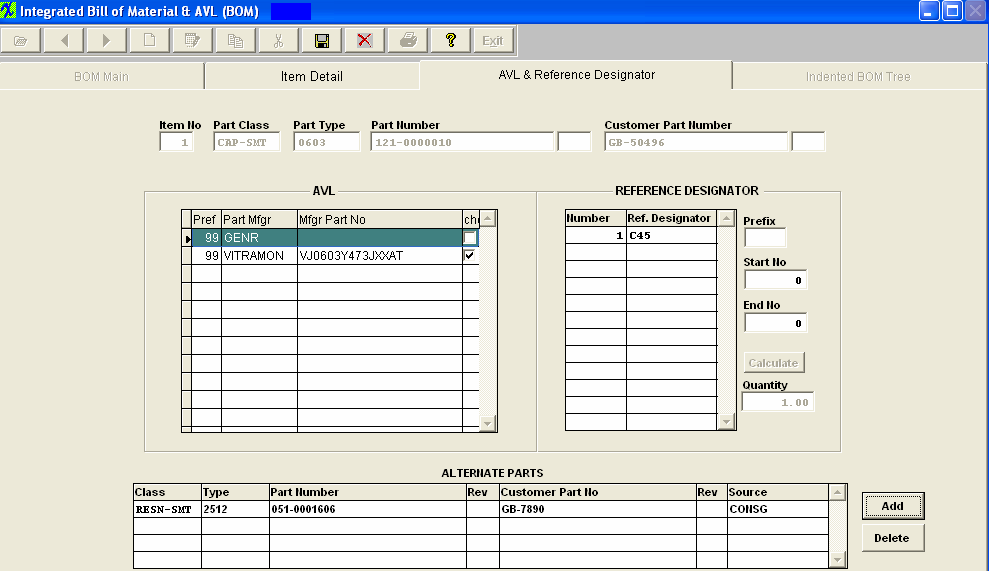
When the user has displayed component parts on the summary screen, and has highlighted one of the parts, pressing on the AVL & REF Tab will display Part Manufacturer and Reference Designation information about the component part.  The NEXT and PRIOR buttons are activated in the AVL Information Tab. Clicking on either button will display the AVLs of the next component in the BOM.


The first row of Information displays the selected detail part information.The Customer Part Number will be displayed if entered in the Item Master.

The Left Center portion of the screen displays the Approved Vendors List (AVL). These manufacturers and their part numbers have been selected and designated as approved sources for this particular BOM assembly.  When the BOM for the assembly has a customer assigned to it, then Manex will pull the approved AVL's from the customer side NOT the Internal side. If no customer is assigned to the BOM then the AVL’s will be pulled from the internal side.   For further detail see Article #2560 .   NOTE:  If "GENR" is approved on the BOM MRP will consider any inventory for that part even if the AVL is not approved on the BOM. 
 
The left hand column displays the preference order, as assigned in Inventory Control Management.
The right hand column box must be checked for the Kit to issue the part to the Work Order.  (At least one AVL must be selected as approved within the BOM module before save will be allowed).

The Right Center portion of the screen displays the reference designators assigned to the component. These fields are optional, but must be completed if reference designator information is to be used in the quality defect collection information.  (The ref designators are case sensitive).

The bottom portion of the screen is available to list alternate parts that may be used in the absence of the primary part. However, these alternate parts are not listed on kit lists, and are only displayed on this screen. On the BOM, Manex provides a place for users to identify “Alternate Part” for each part called out in the BOM. However, this is for information and cross reference ONLY and there is no connection with the MRP, Purchasing or Kitting, etc. modules. The concept here is that if the engineers want to include alternate (not preferred, and not on AVL) parts for the possibility that in case purchasing can’t get the original parts called for by MRP, they could look up the alternate part on the BOM, and then order that part. However, to get the part into the kit, they will have to add the alternate part as a line shortage to the Work Order, and also check the “ignore shortage” for the part(s) originally required and short on the Work Order. Then MRP will work as needed, and the kit will show the alternate part as a (line) shortage until filled. Incidentally, creating the line shortage and checking the ignore shortage for the original part will result in an MRP directive (the next time it is run) to buy the alternate (line shortage) part. Please refer to the Material Requirements Planning and the Kitting, Allocating & Shortage Management modules.

AVL & Ref Designator Field Definitions

COMPONENT INFORMATION

Item No The item number assigned to the components in the BOM.
Part Class

The Part Class of the component part.

Part Type

The Part Type of the component part.

Part Number

The component part number.

Rev The Revision number of the component.

Customer Part Number

The customer part number as entered in the Item Master.

Rev

The Revision number of the customer’s part number.

AVL INFORMATION

Pref

The order of preference number.

Part Mfgr

An approved manufacturer for the component on the current BOM.  NOTE:  When the BOM for the assembly has a customer assigned to it, then Manex will pull the approved AVL's from the customer side NOT the Internal side.   If no customer is assigned to the BOM then the AVL’s will be pulled from the internal side.   For further detail see Article #2560 .

Mfgr Part No

The commercial part number.

Checkuse

This box must be checked for kitting to pull the component.   NOTE:  If "GENR" is approved on the BOM MRP will consider any inventory for that part even if the AVL is not approved on the BOM.  (At least one AVL must be selected as approved within the BOM module before save will be allowed).

REFERENCE DESIGNATOR INFORMATION

Number

The sequential number assigned to each occurrence of the component on the assembly.

Ref Designator

The assigned location for each occurrence of the part. (The ref designators are case sensitive).

Prefix A prefix assigned to reference designators for the current component. Is usually a “C” for capacitors, “R” for resistors, etc
Start No

If the user wishes to fill in the reference designators automatically, then the start number will be the beginning number in the sequence of reference designators assigned.

End No

If the user wishes to fill in the reference designators automatically, then the end number will be the last number in the sequence of reference designators assigned.

Pressing the Calculate button will fill in all reference designators with the prefix plus incremental numbers beginning with the start number entered.
Quantity

The quantity of components used in the assembly.

ALTERNATE PART INFORMATION

These items are the same as previously described.

DIRECTIVE BUTTONS


Pressing the Add button in the ALTERNATE area will allow the user to add additional item master part numbers as approved alternates.


Pressing the Delete button in the ALTERNATE area will allow the user to remove item master part numbers as approved alternates.

1.4. Indented BOM Tree Tab
When the user has displayed component parts on the BOM Main screen, and has highlighted one of the parts, pressing on the Indented BOM Tree tab will display the components with additional information about a make part components. 
 
The first row of data reminds the user of the assembly information.

The bottom portion of the screen displays the components of this assembly. If there is a plus sign to the left of a listed component, click on the plus sign and the components of the listed
components will also appear.