| 1. Fields & Definitions for SFT by WO |
| 1.1. Work Order Shop Floor Tracking | 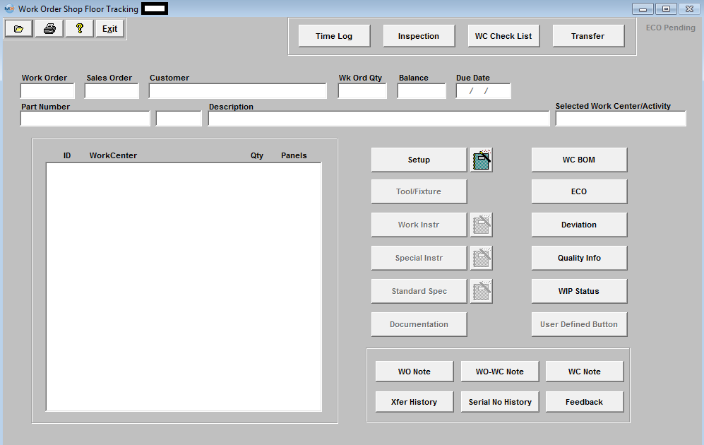
Work Order Shop Floor Tracking Fields and Definitions
 |
This Text/characters turns RED if an ECO (Engineering Change Order) is Added and Saved. When the ECO is approved, this button characters turns back to gray. This criteria is based on the product number and no revision number as the ECO will change the revision number.
This feature has been added because of the importance of the users needing to know that an ECO is being initiated by the production personnel. This will help prevent product being built according to the original instructions and cut down on any additional rework or schedule delays.
|
| Work Order |
The Selected Work Order |
| Sales Order |
The Sales Order linked to the Selected Work Order |
| Customer |
The Customer Name associated with the Selected Work Order |
|
Wk Ord Qty
|
The number of units for the Selected Work Order |
| Balance |
The remaining balance of the parts to be delivered for the work order |
| Due Date |
The due date for the first shipment remaining to be shipped in the work order (ignores due dates that have already been shipped). |
|
Part Number
|
The part number of the assembly being built for the work order. Next to the part number is a space for revision |
| Description |
This field will contain the Class, Type and Description of the assembly being built for this work order. |
| Selected Work Center/Activity |
This area displays the work center (or activity) from which each of the action buttons below are launched.It is selected by placing the cursor (by mouse or tab) on the work center (or activity) of interest. |
| ID |
The ID or abbreviation established for the work center. |
| Work Center |
The Work Center's assigned to the MAKE part in Work Order Traveler Setup |
| Qty |
The quantity of parts pertaining to the work order that are currently in the work center.
|
| Panels |
This field will contain the number of panels in the work center (if the user tracks panels, based on conditions in the Shop Floor Tracking Defaults).
|
See Article #3107 for the Directive Buttons fields and definitons
|
| 1.1.1. Directive Buttons | SFT by WO Directive Buttons
 |
The Time Card module has two functions:1) to enter the worker coming in at the first of the shift and exiting for the day, and 2) to track time spent by each worker on each Work Order (Job), by date and time. This information will forward to the Time and Attendance module. |
 |
See Article #1769 for detail on entering Quality Inspection results using this function. Data may be used to track line quality based on customer, work center, product, location, etc. All Statistical Quality Control information and graphics are based on data entered here. |
 |
Depressing this button will display a list of items defined to be checked as completed for a specific Work Center. The users visit this screen, identify the items completed, and enter their password, marking the check list with their initials and date completed. For further information see Article #3552. |
 |
The key function of this module. This is where the users identify the number of products moved from one work center to another during the production of the work order. For further detail see Article #857 . |
 |
When the Work Center Activity Setup and Run is entered, clicking in this area will provide the user with both text and pictorial instructions for setting up the work center. |
 |
Depressing this button will display any Tool/Fixture information which has been assigned to the Product through the Routing or Product Data Management (PDM) Module. NOTE: For this button to be enabled user MUST have the "Tool/Fixture Released" box checked on the Check List Title screen.
|
 |
When the Product Data Management module is used, clicking in this area will provide the user with both text and pictorial instructions for processing the product in the work center. NOTE: For this button to be enabled user MUST have the "PDM Released" box checked on the Check List Title screen. |
 |
When the Product Data Management module is used, clicking in this area will provide the user with both text and pictorial instructions for the product and work center. The Special Instructions are not printed on the travelers. NOTE: For this button to be enabled user MUST have the "PDM Released" box checked on the Check List Title screen. |
 |
Identifies standard specifications relating to this product per the Standard Process Specification module. NOTE: For this button to be enabled user MUST have the "PDM Released" box checked on the Check List Title screen. |
 |
Provides a list of documents relating to the product being assembled. Displays the document number, revision, document date, and notes about the document. NOTE: For this button to be enabled user MUST have the "PDM Released" box checked on the Check List Title screen. |
 |
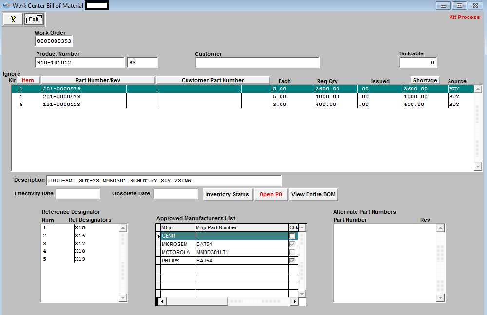
This screen will list all part number assigned to the specific Work Center within the BOM module. It will also allow the user to view the Inventory Status, Open PO's, and Entire BOM if desired. Within these screens you can Sort, Search for specific items, and drill down to Original PO.
Inventory Status - Within this screen you can Sort, or Search for specific items.
Open PO's - Within this screen you can Sort, Search for specific items, and drill down to Original PO.
|
 |
|
 |
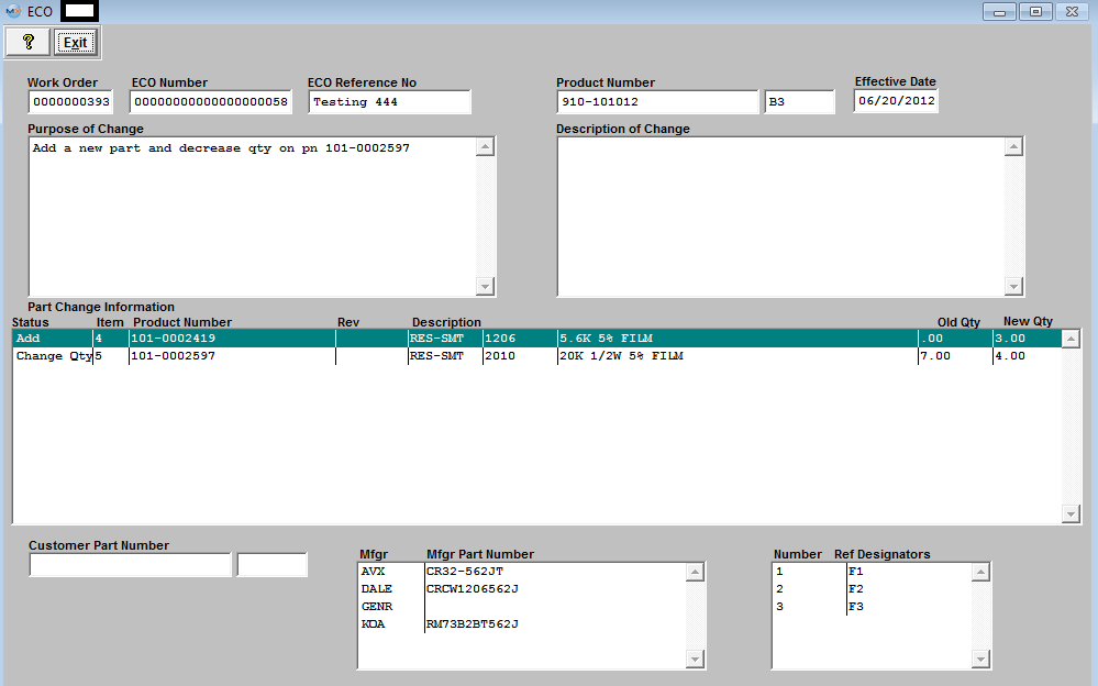
This screen will list the detailed information pulled forward from the ECO Control Management module pertaining to any approved Deviations for the selected product. |
 |
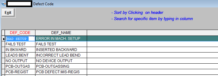
Will display the Quality information for the selected Work Center based on the information entered within the Inspection module.
View All Defect Codes - Within this screen you can Sort, or Search for specific items.
|
 |
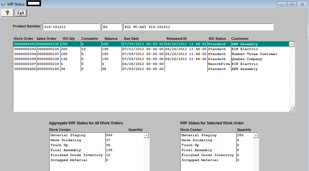
Show all the open work orders for this product and show where the quantities are in the shop floor.
|
 |
This is an outside call program that ManEx has implemented into the system. The Users can have their own program to run when they scan their serial number inside of shop floor tracking by using the “User defined” button. Within the System Setup/Outside Program Calls Setup module, the user will have the ability to change the button name of the “User Defined” button and select which program (EXE) they want to run after the users scans specific Serial Numbers. |
 |
Any notes entered for the work order in the Shop Floor Tracking screen will cause the button to turn Red. Any comments in this area will be visible to all work centers which are included in the work order routing. |
 |
Any notes entered specifically for the work order and the work center being viewed will cause the button to turn Red, calling the user’s attention to review notes that are applicable to the order. This button is sensitive to the work center being highlighted on the shop floor tracking screen. |
 |
Any notes entered for the work center highlighted on the shop floor tracking screen will cause the button to turn Red. Any comments in this area will be visible to all products which include the work center in the routing. |
 |
This button allows the user to view the history of product transfer from one work center to another. NOTE: If the product has changed revisions from the ECO module, the SFT module will see it as a different product and no longer display the Transfer History information on screen for the old revision. (See Article #3401 for more detail).
Note: If product is serialized the transfer history screen will list each product individually, treating each serial numbered product as its own seperate part for tracking purposes, as displayed in the screen below:

If product is not serialized the xfer history will list qty's as they are transfered, as displayed in the screen below:

|
 |
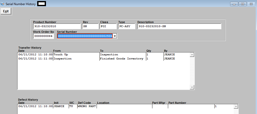
This button will display Transfer History and Defect History by specific serial numbers.
|
 |
This is simply a note screen that may be used to record information about the product during the course of manufacturing, and is specific to the work center and work order. |
|
| 1.2. Transfer Screen | |
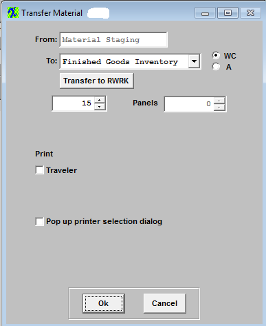
| From |
Work Center Highlighted that product is currently in |
| To |
Work Center that product being transferred to |
| WC/A |
The user may elect to transfer material within work centers (WC) or within activities (A) by pressing the appropriate radio button |
| Transfer to RWRK |
User can click on button to move all qty's in current WC directly to the Rework work center even if they don't have "Skip WC" rights |
 |
Qty of product being transfered |
| Panels |
Number of Panels (if applicable) |
| Traveler |
Check to Print Traveler |
| Pop up printer selection dialog |
Check to have the Printer Pop up selection dialog box appear |
 |
Add any Foot Notes that you would like printed on the Traveler. Note: These notes are not retained in any tables and are only temporary. |
|
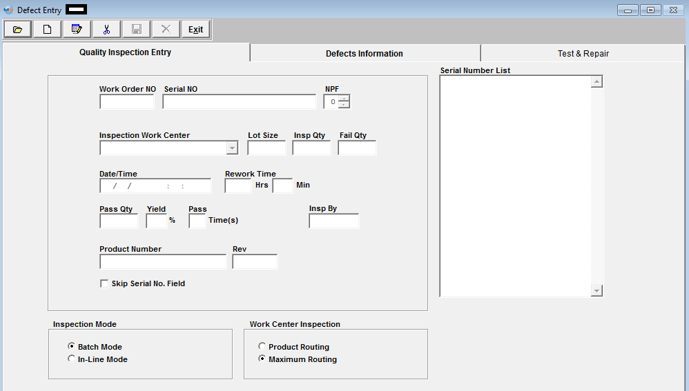
| 1.3. Quality Inspection Entry Tab | Quality Inspection Entry Screen Field Definitions
| Work Order Number |
The Work Order number which was inspected.
|
| Serial Number |
The serial number assigned to the specific assembly unit.
|
| NPF |
The next field, “NPF”, no problems found, is provided for the user to record when observing the product. If the serial number had previously been rejected, and analysis of the product yield no further problem, either with cosmetics or function, then the user may change this number to 1, meaning the first time it was inspected or tested, no problem was found. If the product serial number is subsequently rejected again, and a second inspection finds a problem, the number may be incremented to a “2”. This will alert users to repeated rejections of a product serial number, one or more times with no discernable defects. If the number of times that a part has experienced an NPF (no of problems found) exceeds that established in the Quality Defect Codes setup, the user will receive a warning message and will allow you to proceed on with the Inspection. This is just a notification that the board has passed the maximum NPF cycle.
|
| Inspection Work Center |
This is the name of the Work Center where the inspection took place.
|
| Lot Size |
This is the number of assemblies available for testing.
|
| Insp Qty |
This is the number ofassemblies actually tested.
|
| Fail Qty |
The number of assemblies which failed inspection.
|
| Date |
The date whereby the inspection took place.
|
| Time |
The time (24 hour clock) when the failure was recorded.
|
| Rework Time |
The time estimated to rework the failed assembly |
| Pass Qty |
The number of assemblies which passed inspection.
|
| Yield |
The percentage of assemblies which passed inspection.
|
| Pass Times |
This is the number of times a particular Serial Number can pass through this Inspection screen. In Quality Defect Code Setup, there is a field called :maximum number of inspections/WC”. The user may define how many times a given serial number can pass through a given Work Center. |
| Product Number |
The internal number assigned to the assembly.
|
| Rev |
The revision number associated with the Product Number.
|
| Product ID |
This field is no longer used and is left blank.
|
| Skip Serial Number Field |
This box is checked if the user wishes to do Without Serial Number Inspection.
|
| Enter Serial Number Without Validation |
Only Enabled if user skips regular serial number entry.
This feature has been added to allow the users the ability to inspect Serial Numbers that do not actually exist within the ManEx system. (for example serial number created outside of ManEx, by customer or other software, etc. . .)If the user checks the “Enter serial number without validation” then ManEx does not validate when the users enters the Serial Number. The system just records the entry for later SQC analysis purpose.(note: if the work order is serialized, then the user can not use this feature)
|
| Inspection Mode |
Determines whether inspection is performed via Batch or In Line mode.
Batch mode is used for entering data previously recorded during inspection of the product. When the user chooses to enter defect data in “In-Line” mode with the serial number, the user won’t be able to enter “lot quantity”, “inspection quantity” or “failed quantity”. These fields are all automatically when the user goes into the “Defects Information” tab. However, if the user enters defect data in “batch” mode without the serial number, then the user will be able to enter “lot quantity”, “inspection quantity” and “failed quantity”.
If the user wishes to 100% inspect material, and directly move the passed material to the next routing work center, then the In-Line Inspection mode may be used.
|
| Work Center Inspection |
The user has the option of viewing defects based on the product routing (Product Routing), or to view all defects (Maximum Routing).
|
| Serial Number List |
The numbers of all of the Serial Numbers which were inspected. Depress the Edit button and then highlight the serial number of choice.
|
|
| 1.4. Defect Information Tab | Defect Information Screen Field Defintions
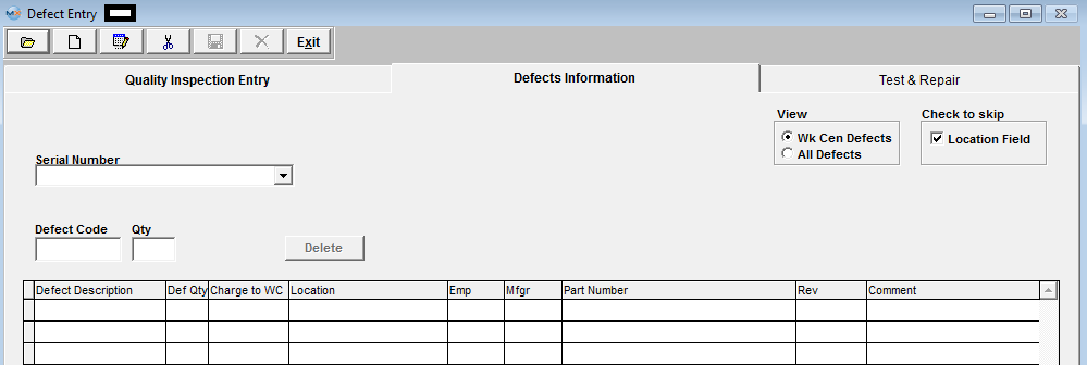
| View |
This displays whether the view of the defects is by Work Center only or covers All defects.
|
| Check to skip location field |
If this box is checked, the location field may be skipped.
|
| Serial Number |
The Serial Number of the failed assembly.
|
| Defect Code |
The code used to describe the defect. This code must be setup in the Quality Defect Code Setup module with System Setup.
|
| Defect Description |
The description of the defect will default in from the Quality Defect Code Setup module when the Defect Code is entered.
|
| Def Qty |
The number of defects will be defaulted on from the Quality Inspection Entry Screen.
|
| Charge to WC |
Enter the Work Center where the defect will be charged.
|
| Location |
Enter in the Reference Designator as set up in the assembly’s Bill of Materials.
|
| Emp |
Select the Employee number assigned to the defect from the pull down. |
| Mfgr |
The name of the manufacturer of the component. Once a Reference Designator is entered a popup screen will be displayed, and user may select a Mfgr.
|
| Part Number |
The internal number assigned to the component, will default in once the Reference Designator is entered.
|
| Rev |
The revision number pertaining to the internal part number will default in once the Reference Designator is entered.
|
| Comments |
Additional comments entered by the user.
|
|
|

