| 1. Test & Repair (T & R) (OPTIONAL Module) |
| 1.1. Prerequisites for the T & R Module |
|
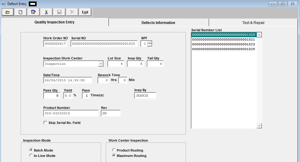
The Test & Repair is actually a separate OPTIONAL module, but has been included into the Defect Entry screen for ease of use for the operators. After activation, Work Order Shop Tracking, Defect Code Entry, and Test & Repair access for each user must be setup in the ManEx Security module. Users with “supervisor’s rights” will automatically have access. To use Test & Repair Management module, Serial Numbering is REQUIRED. This information is entered using the Work Order Management Serial Number Control module. |
| 1.2. Introduction for the T & R Module |
Test & Repair Management (T&R) has been designed to capture testing results and failure information such as: In-circuit Testing, Sub-Assembly Functional Testing and System Final Assembly Testing. Once this information has been entered this will allow the users the ability to see the Serial Number History and view all of the testing and repair results as well as when it had been shipped to customers. It will also keep track of any associated returns or warranty work that had been done against this particular Serial Number, continuing history as long as the unit is in service.
|
| 1.3. Fields & Definitions for the T & R Module |
| 1.3.1. Test & Repair Tab | ||||||||||||||||||||||||||||||||||||||||||||||||||||||||||||
Test & Repair Screen Field Definitions
The Test & Repair is actually a separate OPTIONAL module, but has been included into the Defect Entry screen for ease of use for the operators.
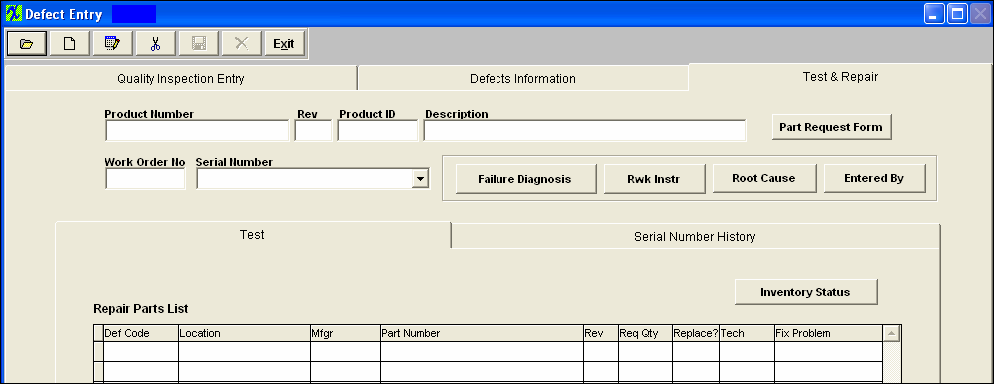
The internal number assigned to the assembly. The revision number associated with the Product Number. This field is no longer used and will be left blank. The description of the Product Number. If the component part is to be replaced, this button will be available to view and print the request for replacement. The number of the work order which was inspected. The serial number of the assembly which failed inspection. Test Tab Field Defintions Repair Parts List
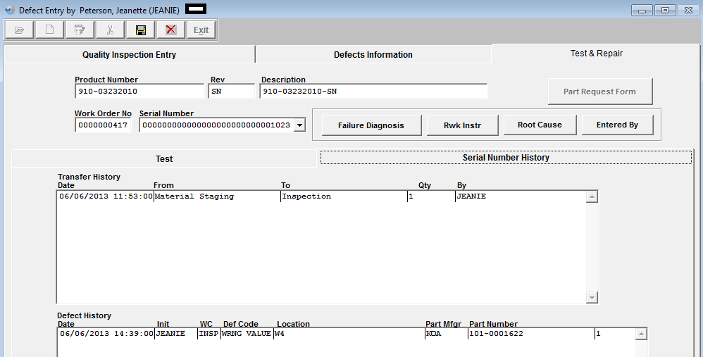
Serial Number History tab 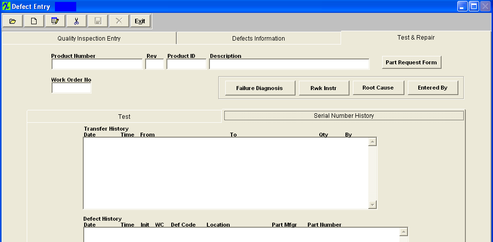 Transfer History Section
Defect History Section
|


| 1.4. How To ...... for the T & R Module |
| 1.4.1. Add Test and Repair Information | ||||||||
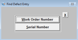
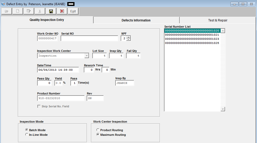
When the user has completed the Defect information, they may enter the Test & Repair tab to enter more information about the part, or may depress the Open/Find record button to find this information at a later time.
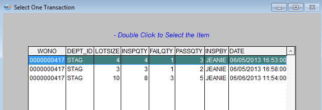
Once user has selected a transaction the following screen appears displaying the record you selected:
 Depress the Edit button and enter your password, user may at this time edit the Quality Inspection Entry info, the Defects Information, or the Test & Repair info:
 Depress the Defects Information Tab: Select the record from the pull down to view in the Test and Repair Tab
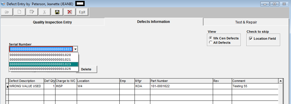 Depress the Test & Repair Tab: (System will only display information for one serial number at a time).
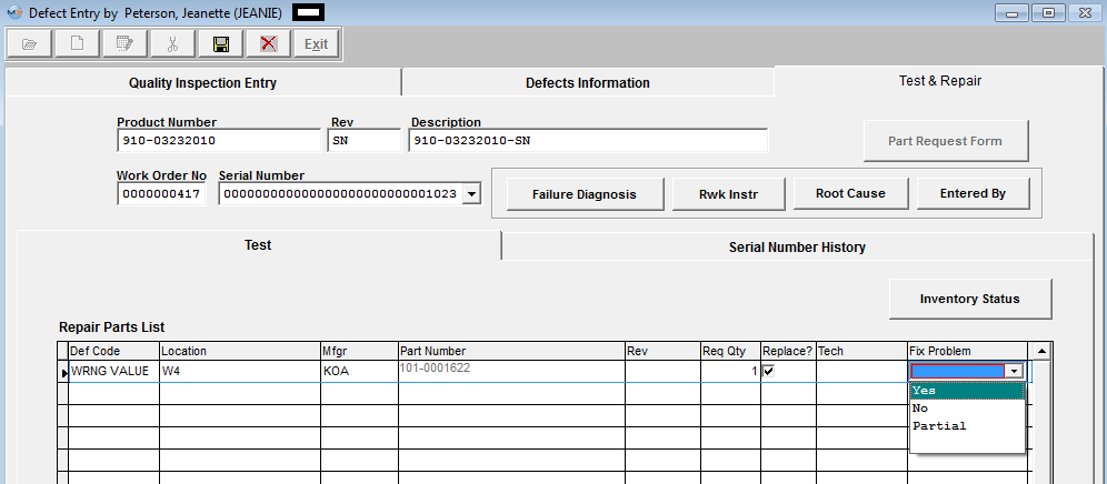
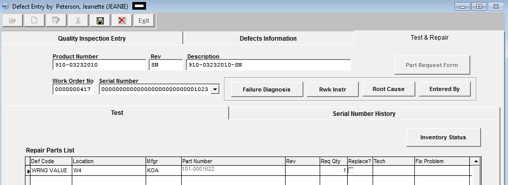 In the edit mode user can edit the required qty, check the Replace? box, and select to Fix Problem from the pull down:
NOTE: To have the USER ID of the technician who fixed the defect displayed, user must double click in the field.
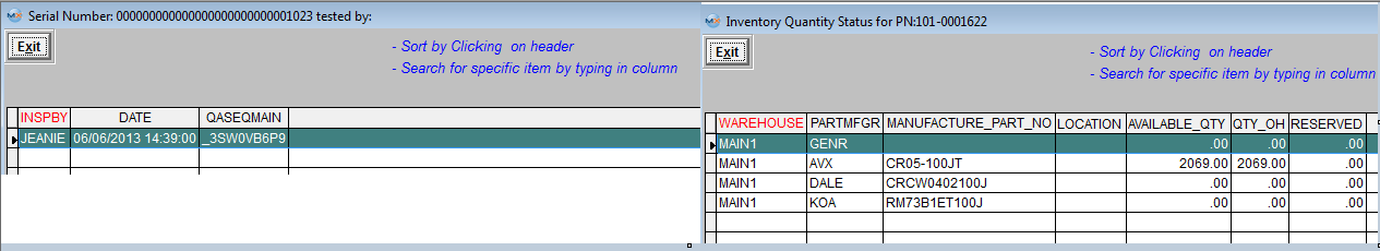
User may enter information in the Failure Diagnosis, Rwk Instructions, and/or Root Cause (these 3 fields are text fields). Within this screen you may also View the "Entered By" or "Inventory Status" of Part Number.
 To View the Serial Number History depress the "Serial Number History" tab.
 Depress the Save button to save changes or Depress the Abandon changes button to abandon changes.
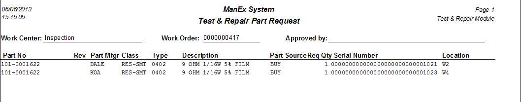
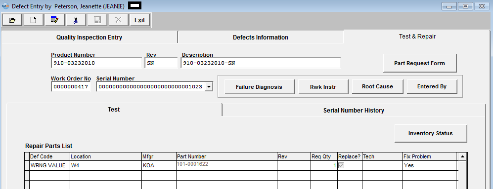 Upon the Save the "Part Request Form" button will become enabled. User may at this time print the "Part Request Form" which will need to be approved and hand delivered to the stockroom, so they may fill the shortage(s) and issue part(s) to the kit.
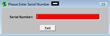
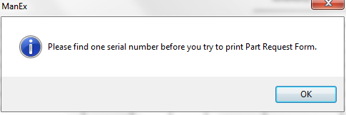
 If a Serial Number is not found for the part being replaced the following message will be displayed.
 |