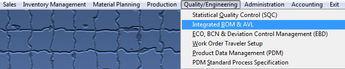
| 1. Quality/Engineering |
| 1.1. Statistical Quality Control (SQC) (OPTIONAL Module) |
| 1.1.1. Prerequisites for SQC | ||||||||||||
Required Prerequisites:
ManEx’s standard module configuration allows most users to accomplish their daily tasks. For those users wanting to get more from ManEx by leveraging the total solutions, this is one of the optional modules available for purchase. To place an order or to learn more about this specific module or any of the other optional modules please contact us at http://manex.com\contactus.aspx After activation, "Statistical Quality Control" (SQC) access for each user must be setup in the ManEx Security module. Users with “Supervisor Rights” will automatically have access.
Optional Prerequisites:
|
| 1.1.2. Introduction for SQC |
The STATISTICAL QUALITY CONTROL (SQC) Module ~ Defect Entry screen is used to record defects and inspection results during the movement of product through the production Work In Process (WIP). The user has a choice of entering data in a batch mode or in an in-line mode See Article #5113 for further detail. Batch mode is the entry of data accumulated during an inspection period, and is data entry only (does NOT transfer product from one work center to another). In-line mode is where inspection is done at the end of a work center or activity, and the product is to be moved to another work center based on the results of the inspection. In-line inspection would require inspection of 100% of the product, in order to move the product from one step to another. It also requires the use of a ManEx workstation at the inspection station, so the data may be entered real-time. Defect entry is based on having a standard nomenclature for the defects in the Quality Defect Codes setup, so that the users do not have the option of creative descriptions. The defects in the setup may be ascribed to specific work centers, to minimize the number of defects that an inspector (or data entry person) has to view to find the appropriate defect. Defect information may be recorded by work order and/or by serial number. Defects may be associated with a specific “location” (reference designator) on the assembly, providing the user has entered reference designators for the assembly in its Bill of Material . If the user chooses to enter reference designator locations for the defects, and has entered reference designators on the Bill of Materials, then ManEx will prompt the user to select the manufacturer for the part used at the location, as well as automatically enter the internal part number at that location. There is also provision for tracking the diagnostics and repair of each defect and assembly. The user may view the history of the assembly’s movement through production, and all of the defects associated with each assembly. |
| 1.1.3. Fields & Definitions for SQC |
| 1.1.3.1. Defect Data Collection |
| 1.1.3.2. View Chart Tab |
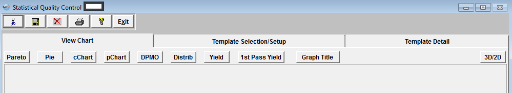 See Article #5115 for more detail on each individual Chart Listed at the Top. Once you have selected the type of graph you wish to view the graph will be displayed in the window below the selection.
|
| 1.1.3.3. Template Selection/Setup Tab |
Template Selection Setup
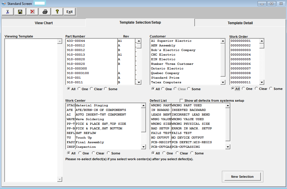
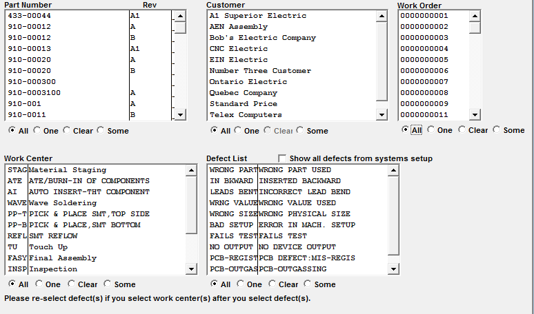
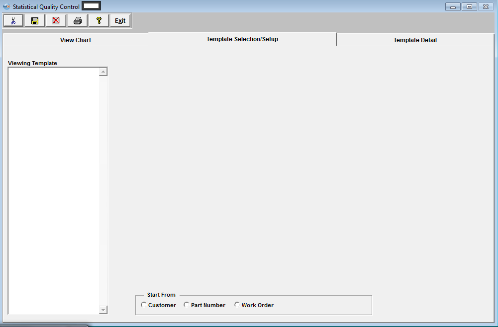 This is the first screen to be used in the module. In this screen, STATISTICAL QUALITY CONTROL graphics are created by selecting parameters to be considered in the graph. This screen operates differently than all other ManEx screens. When bringing up the SQC module, the user is first presented with a template screen from which to choose parameters to be included in the information displayed. When the user enters the system, he/she may select how they want to start the process of selection. Click on the Customer, Part Number or Work Order radial. |
| 1.1.3.4. Template Detail Tab | ||||||||
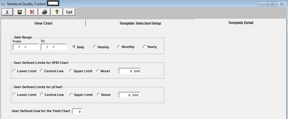
Template Detail Tab
|
| 1.1.4. How To .... for SQC |
| 1.1.4.1. Enter the Defect Data Information |
All data must be Entered in the Quality Inspection Entry and Defect Information screens, with in the Shop Floor Tracking Module.
|
| 1.1.4.2. Enter the Defect Data Information for the DPMO by Employee Report |
In order to have the "DPMO by Employee" report create valid data, the user must be sure to enter the opportunities for defects (PPM) in the Work Order Traveler Setup and the employee must inspect the board and be assigned to the defects. The "DPMO by Employee" report only gathers data if BOTH "Inspected By" and "Emp" are the same user, and the PPM is setup. See Article #3156 for further detail on DPMO. The following steps need to be followed to collect and track defects per employee. All data must be Entered in the Quality Inspection Entry and Defect Information screens, with in the Shop Floor Tracking Module.
|
| 1.1.4.3. SQC - Setup an SQC Template | ||||||||||||||||||||||||||||||
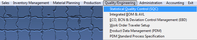
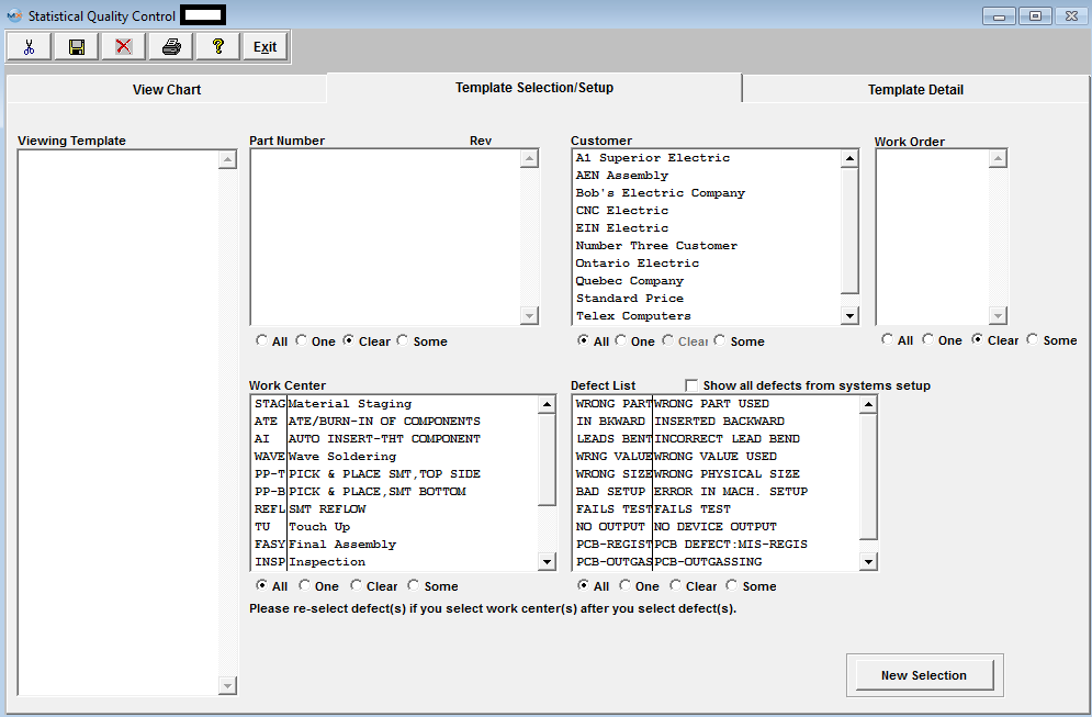
Enter the SQLMANEX.EXE (within the ManEx root directory) The following screen will be displayed, select Quality/Engineering/Statistical Quality Control (SQC) Module The following screen will be displayed:
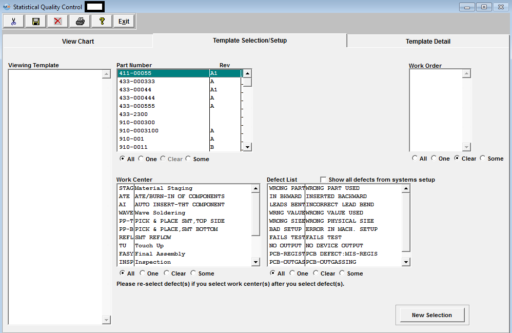
Template Selection Setup This is the first screen to be used in the module. In this screen, STATISTICAL QUALITY CONTROL graphics are created by selecting parameters to be considered in the graph. This screen operates differently than all other ManEx screens. When bringing up the SQC module, the user is first presented with a template screen from which to choose parameters to be included in the information displayed. When the user enters the system, he/she may select how they want to start the process of selection. Click on the Customer, Part Number or Work Order radial.
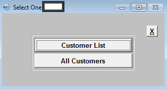
Clicking on the Customer radial will bring up the following selection screen:
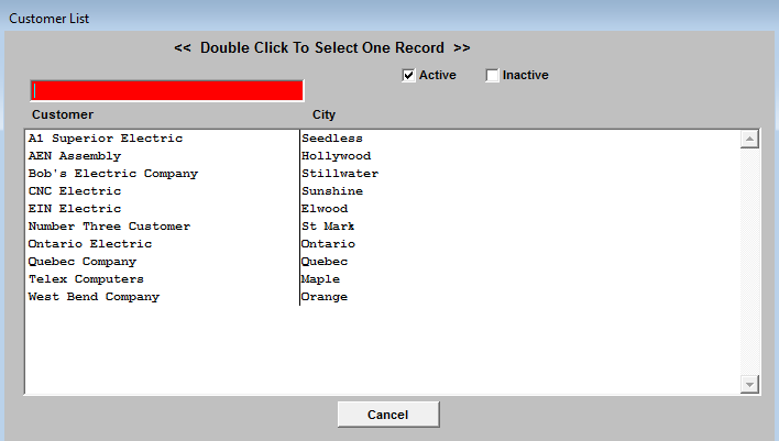
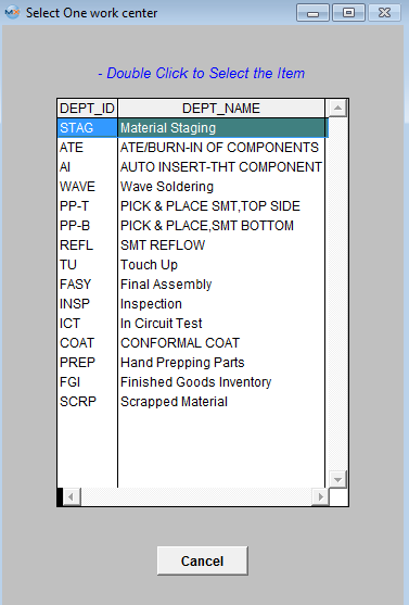
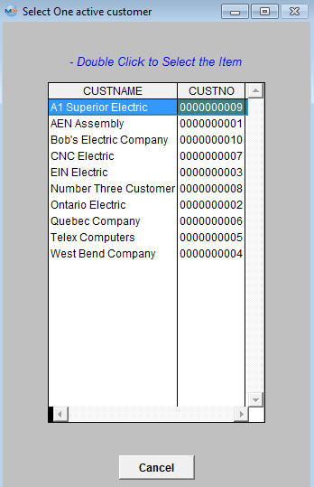
Selecting by Customer List will bring up the following selection screen: Type the Customer into the red box or highlight and double click.
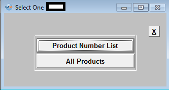
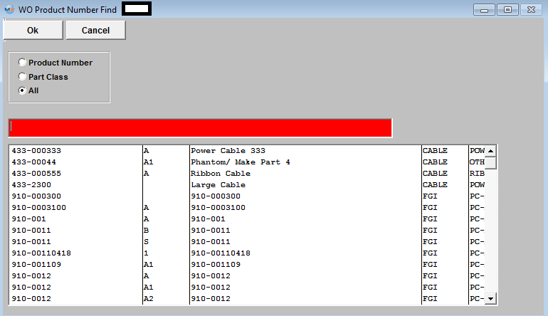
If the user selects Product Number List, the following list will appear: Type the Part Number into the red box or highlight and double click.
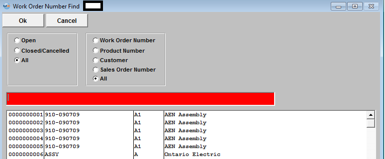
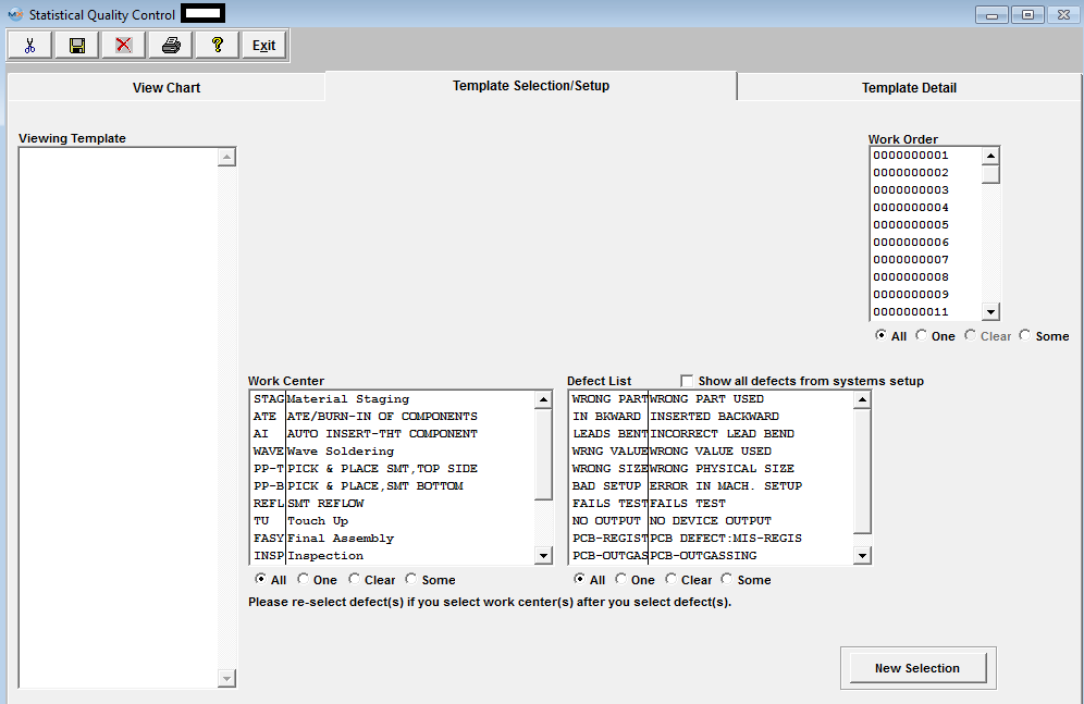
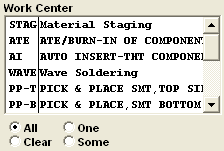
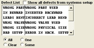
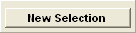
In the Work Order section, choose from All, One or Some. If you’ve selected one, highlight the desired work order. If you want more than one, depress the Ctrl key and click on the ones desired. In the Work Center section, choose from All, One or Some. If you’ve selected one, highlight the desired work center. If you want more than one, depress the Ctrl key and click on the ones desired. Make the same selection in the Defect List section. If you want all defects displaying as per the System Setup, check the Defect List box. To make a new selection, depress the New Selection button. Template Detail Screen Pressing on the Template Detail tab brings up the following screen:
Enter the Date Range, From and To. Mark the Radial for the view by Daily, Weekly, Monthly, or Yearly. Mark the radial for the User Defined Limits for DPMO chart: Lower Limit, Central Line, Upper Limit or Reset. Indicate Central Line amount in box. Mark the radial for the User Defined Limits for pChart: Lower Limit, Central Line, Upper Limit or Reset. Indicate Central Line amount in box. Indicate the user defined goal for the Yield Chart.
To Save this template for future use go back to the Template Selection/Setup tab enter in a name and depress the Save button. The Template will be saved in the Viewing Template field for future use.

|


| 1.1.4.4. SQC - Data Viewing And Analysis | ||||||||
Enter the SQLMANEX.EXE (within the ManEx root directory) The following screen will be displayed, select Quality/Engineering/Statistical Quality Control (SQC) Module The following screen will be displayed:
Template Selection Setup This is the first screen to be used in the module. In this screen, STATISTICAL QUALITY CONTROL graphics are created by selecting parameters to be considered in the graph. This screen operates differently than all other ManEx screens. When bringing up the SQC module, the user is first presented with a template screen from which to choose parameters to be included in the information displayed. When the user enters the system, he/she may select how they want to start the process of selection. Click on the Customer, Part Number or Work Order radial.
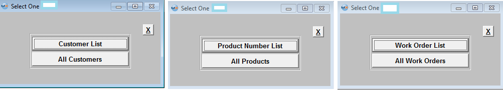 The user then may select to view just a Customer List, Product Number List, Work Order List, or All Customers, All Products, or All Work Orders.
Once they have made their choice, the following screen will appear. Depending on the selection the following screen may differ.
In each section, choose from All, One, Some, or Clear. If you’ve selected one, highlight the desired. If you want some (more than one), depress the Ctrl key and click on the ones desired. To make a new selection, depress the New Selection button. Template Detail Screen Pressing on the Template Detail tab brings up the following screen:
Enter the Date Range, From and To. Mark the Radial for the view by Daily, Weekly, Monthly, or Yearly. Mark the radial for the User Defined Limits for DPMO chart: Lower Limit, Central Line, Upper Limit or Reset. Indicate Central Line amount in box. Mark the radial for the User Defined Limits for pChart: Lower Limit, Central Line, Upper Limit or Reset. Indicate Central Line amount in box. Indicate the user defined goal for the Yield Chart. View Chart Screen/Graphs Pressing on the View Chart brings up the Graphics Display Window. Defect Pareto Chart - The results being displayed in the Pareto Chart are from Several Work Orders combined. Note: The yellow line is a cumulative % of total defects represented by the current defect and all preceding defects. That is why it reaches 100% by the right side of the graph.
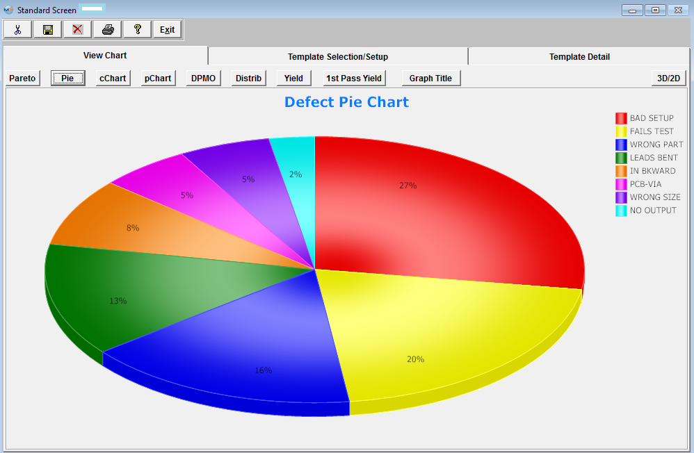
 Defect Pie Chart - The results being displayed in the Defect Pie Chart are from several Work Orders Combined.
 cChart - The results being displayed in the cChart are from all Work Orders, Work Centers, and all defects from 01/01/2012 thru 01/31/2012 (1 month)
The Red Line is the Defect Qty The formula for the Central line (Green line) is: c = Total Defects (divided by) Number of Subgroups The formula for the Upper Control Limit (UCL) (Blue line) = c + 3 (divided by) p The formula for the Lower Control Limit (LCL) (Yellow line) = c - 3 (divided by) p (or 0, whichever is greater)
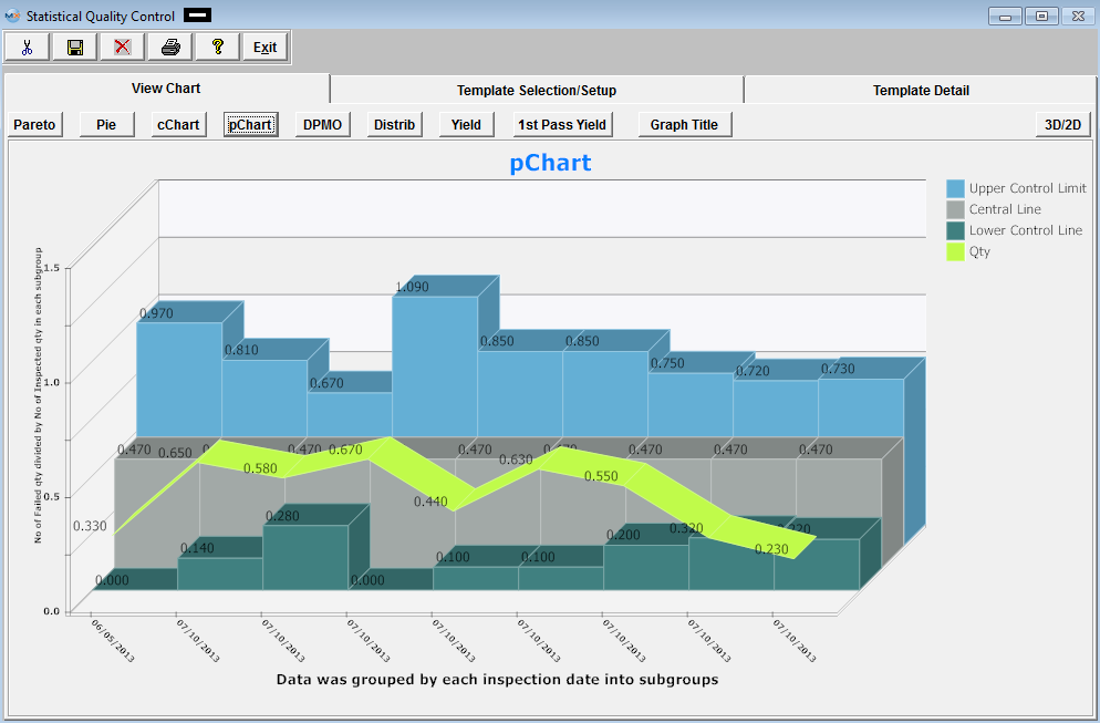
 pCHART The results being displayed in the pChart are from all Work Orders, Work Centers, and all defects for one day 07/10/2013.
The formula for the Central line (Gray) is: p = Total Number Failed (divided by) Total Number Inspected The formula for the Upper Control Limit (UCL) (Blue) = p + 3 (divided by) p (1-p) divided by n The formula for the Lower Control Limit (LCL)(Green) = p - 3 (divided by) p(1-p) divided by n (or 0, whichever is greater)
DPMO (Defects Per Million Opportunities) Chart (Which means the number of things wrong observed in the inspection of a part, or board assembly). The results being displayed in the DPMO Chart are from several Work Orders combined.
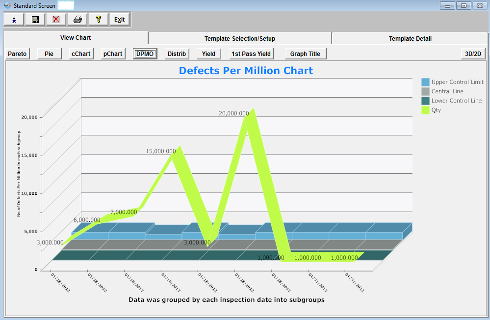 Defects Per Million Opportunities. There are several ways to setup the opportunities (which means the number of possible defects that can occur on a product), but it is up to each company to make that decision. For Example: Some may say that a resistor with two leads that are not properly soldered is counted as two defects and some may only count it as one defect, since it is one part that was assembled incorrectly. The opportunity or the standard opportunity is entered in the Work Order Traveler Setup module. The field is called PPM = Parts per million. The DPMO chart uses the PPM as a reference to measure the actual failures against the total inspected quantity. See Article #3156 for further detail on DPMO. The formula for calculating DPMO chart is as follows: Example (2+3+3) = SUM of defect quantities (8) * opportunities or PPM (1,000,000) (divided by) Qty Inspected (500) (divided by) parts per unit (100) = 160 Daily, Weekly, Monthly, Yearly On the Y axes the graph shows number of defects per million One the X axes day or week or month or year This graph collects defect information for the selected work centers and work orders in the selected date range. The user also has to select if the information will be grouped by day, week, month, or year. The selected group will be your X coordinates on the graph. The Y coordinates will be calculated as sum of the defect quantities *opportunities or PPM divided by total Qty inspected (divided by) parts per unit (qty was entered in the routing module) grouped by X coordinate unit (Daily, weekly, monthly, yearly). This is a data line there is three more control lines displayed on the graph: Central control line: Upper control line: Lower control line All three lines could be user define lines. If the lines are not user define lines they calculated as following Central Line lnCentralLine=lnTotalDef/lnTotalComp, where lnTotalDef is sum of all defect quantities * 1000000 and lnTotalComp is sum of inspected quantities*Parts Per Unit (entered in the routing module) At this time system will decide if it can use average group size or not. If the size group varies more tan 15% the system will use variance Upper and Lowercontrol limit. If average group size could be used the average group size gets calculated by taking lnAvrgSubgrSize=lnTotalComp divided by number of groups and rounded to the nearest integer. Calculation for the Upper Control Line LnUpperLine=ROUND(((3*(SQRT(lnCentrLine*(1000000-lnCentrLine))))/SQRT(lnAvrgSubgrSize)),3) Calculation for the Lower Control Line lnLowerLine = ROUND(lnCentrLine -((3*(SQRT(lnCentrLine*(1000000-lnCentrLine))))/SQRT(lnAvrgSubgrSize)),3) lnLowerLine = IIF(lnLowerLine<0,0,lnLowerLine)
Defects Distribution Chart - The results being displayed in the pChart are from all Work Orders, Work Centers, and all defects from 01/01/2012 thru 01/31/2012 (1 month)
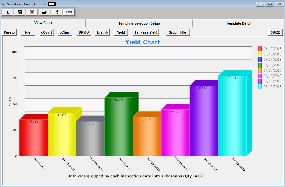
 Yield Chart - "Yield" = Total number of units handled correctly through the process step(s). This is usually measured in a percentage. The results being displayed in the "Yeild Chart" is the ratio of summed inspected qty and summed passed qty, grouped by date (user can select WO number, defect code to be filtered). The results below are from One Work Order, All Work Centers, and all defects for one day 07/10/2013.
1st Pass Yield Chart The results being displayed are from all Work Orders, Work Centers, and all defects from 01/01/2012 thru 01/31/2012 (1 month). 1st Pass Yield chart in the SQC module is designed only when the serial number is used for the work order. The system uses the serial number to determine how many serial numbers passed without failure/defects within a work order. 1st Pass Yield chart will be blank if there are no product tracked by serial number within the production floor 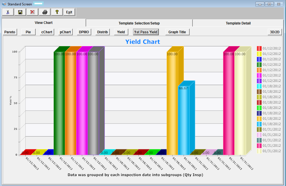
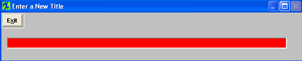
To enter a new title, depress the Graph Title button. The following will be displayed:
Enter in the new desired Graph Title. Depress the Exit button, and the graph title will be updated. 
|
| 1.1.5. FAQ's for SQC |
| Facts and Questions for the Statistical Quality Control Module |
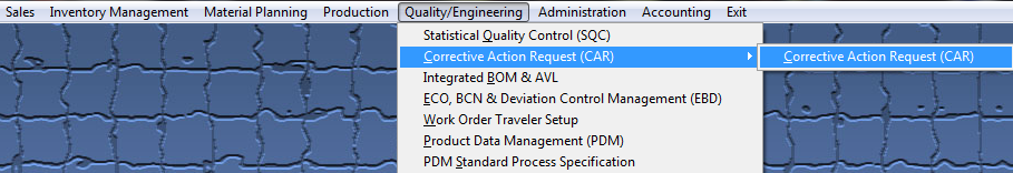
| 1.2. Corrective Action Request (CAR) (OPTIONAL Module) |
| 1.2.1. Prerequisites for CAR | ||||||||||||||||||
Prerequisites Required for Entering a New Corrective Action Request:
ManEx’s standard module configuration allows most users to accomplish their daily tasks. For those users wanting to get more from ManEx by leveraging the total solutions, this is one of the optional modules available for purchase. To place an order or to learn more about this specific module or any of the other optional modules please contact us at http://manex.com\contactus.aspx
After activation, "Corrective Action Request" (CAR) access for each user must be setup in the ManEx System Security module. Users with “Supervisor Rights” will automatically have access.
|
| 1.2.2. Introduction for CAR |
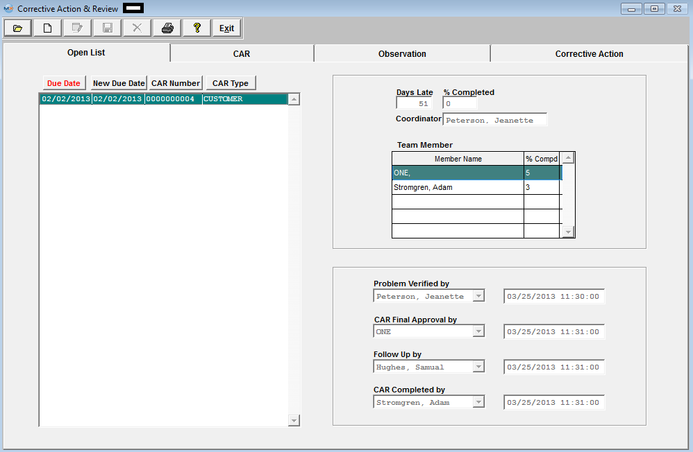
The Corrective Action Request (CAR) module is used to record and track to the conclusion of all corrective action requests. The user may establish his/her own type(s) of corrective actions in the system setup. Examples of types of corrective actions may be Supplier, Customer, Production, Administration, etc. In addition to classifying corrective actions by type, the user may also establish number types for the corrective action. Examples of number types might be RMA, DMR, Internal, etc. The user enters information relating to each CAR including ISO reference, Quality Manual Descriptions, Customer/Supplier information and/or Work Center/Department involved. There is provision for text entry of the Description of Condition, the Apparent Cause, and the Actual Cause, along with provision to enter a graphics image. In the Corrective Action section, there is provision to enter Corrective Action Taken, as well as information for Follow Up & Review. In the Main screen, a list of all open corrective actions is displayed, and may be sorted by Due Date, New Due Date (if revised), CAR number or CAR Type. There is provision to enter the name of the CAR Coordinator, and include a list of team members and their percent completion of the task. There is also a place for users to enter the date and name of the team member who verified the problem; the date and name of the team member who granted the final approval of the CAR; the date and name of the team member who followed up on the CAR; and the date and name of the team member who closed the CAR.
|
| 1.2.3. Fields and Definitions for CAR |
| 1.2.3.1. Open List Tab | ||||||||||||||||||||||||||||
This is the due date for the open CAR. (The user may sort on this field by depressing the Due Date button.)
|
| 1.2.3.2. CAR Tab | |||||||||||||||||||||||||||||||||||
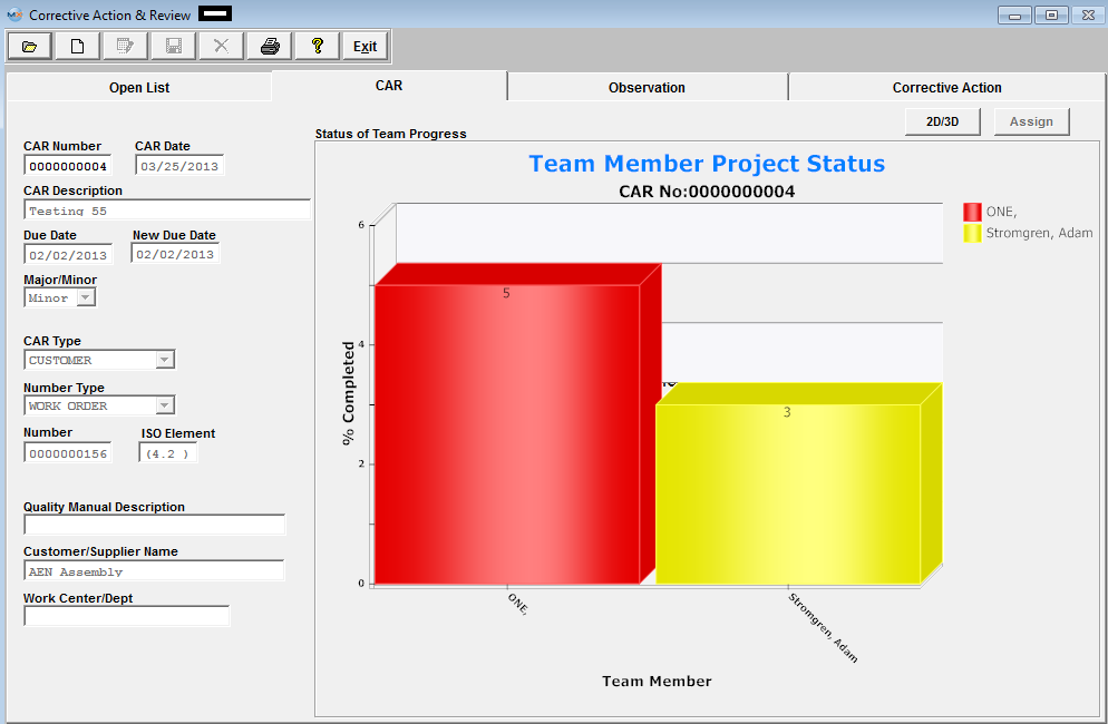
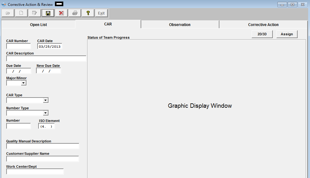
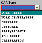
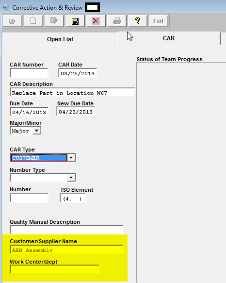
The number assigned to the Corrective Action Report. The due date of the Correction Action. If revised, the revision due date. Describes whether the corrective action is major or minor. The type of CAR number as set up in system setup.Please refer to the Implementation – Production manual. Status of Team Progress section
If some work has been completed by the team and registered in the Open List tab, a graph displaying the percentage of completion by each team member will display. Depress this button to change graph view to 3D or back to 2D.
|
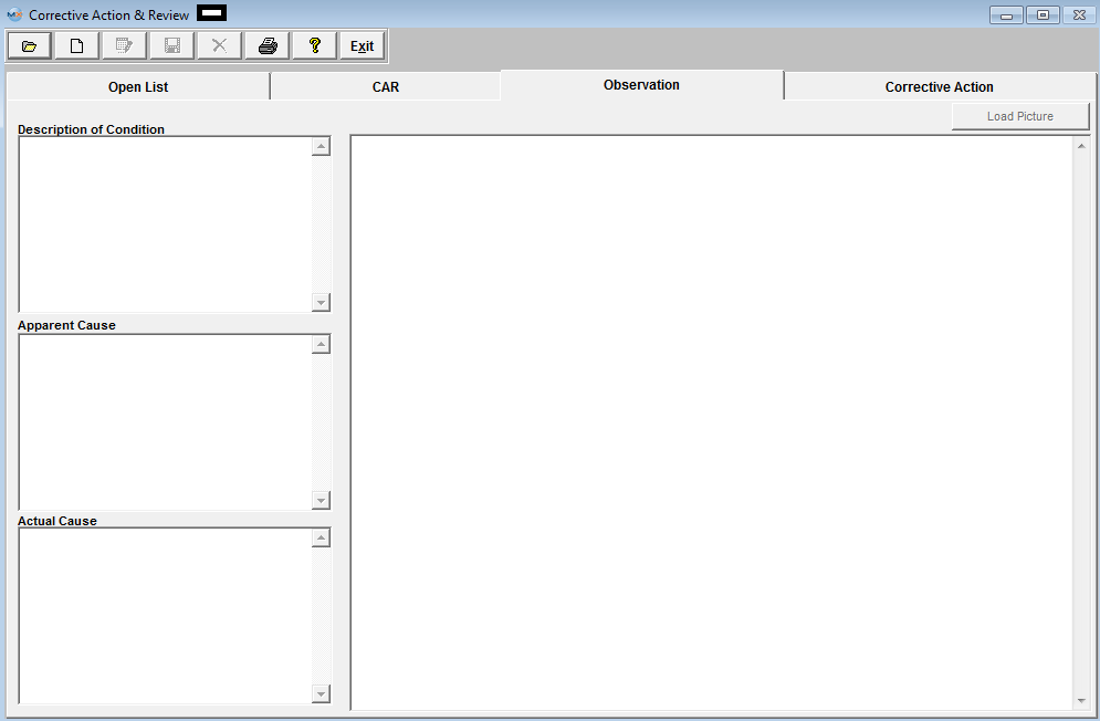
| 1.2.3.3. Observation Tab | ||||||||
This field is for the user to enter in the description of the condition for the CAR being created. This field is for the user to enter in the actual cause for the CAR being created. This button is available for the user to Load a picture for the CAR being created if applicable. |
| 1.2.3.4. Corrective Action Tab |
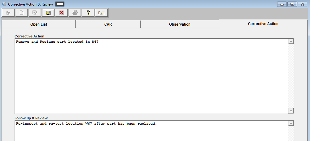
This tab is available for user to add notes regarding Corrective Action, and Follow Up and Review for a specific CAR. 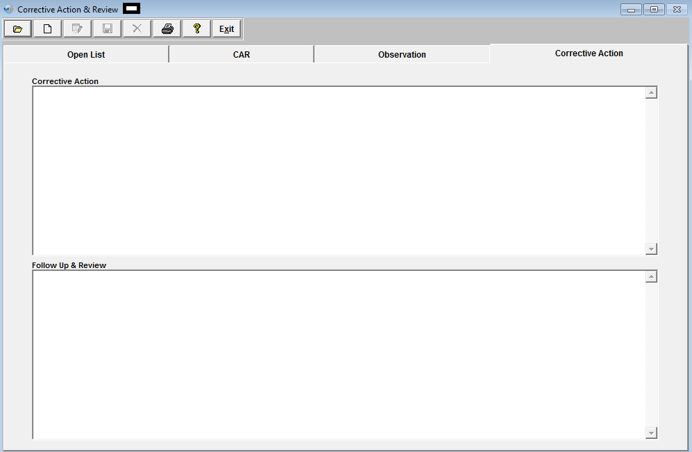 |
| 1.2.4. How To ..... for CAR |
| 1.2.4.1. Finding A Corrective Action Request Record | ||||||||||||||
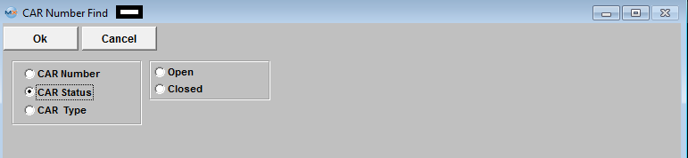
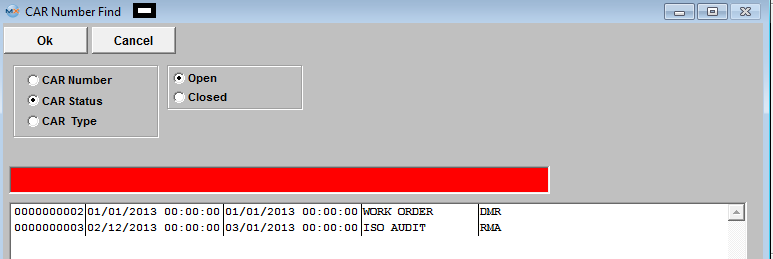
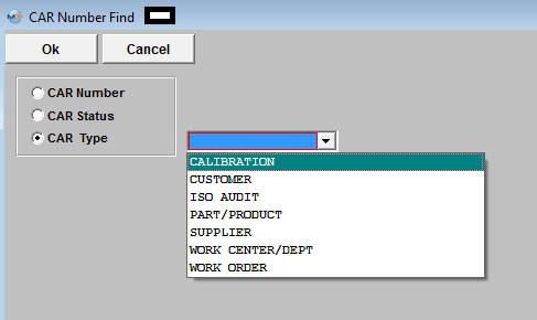
The following screen will be displayed: 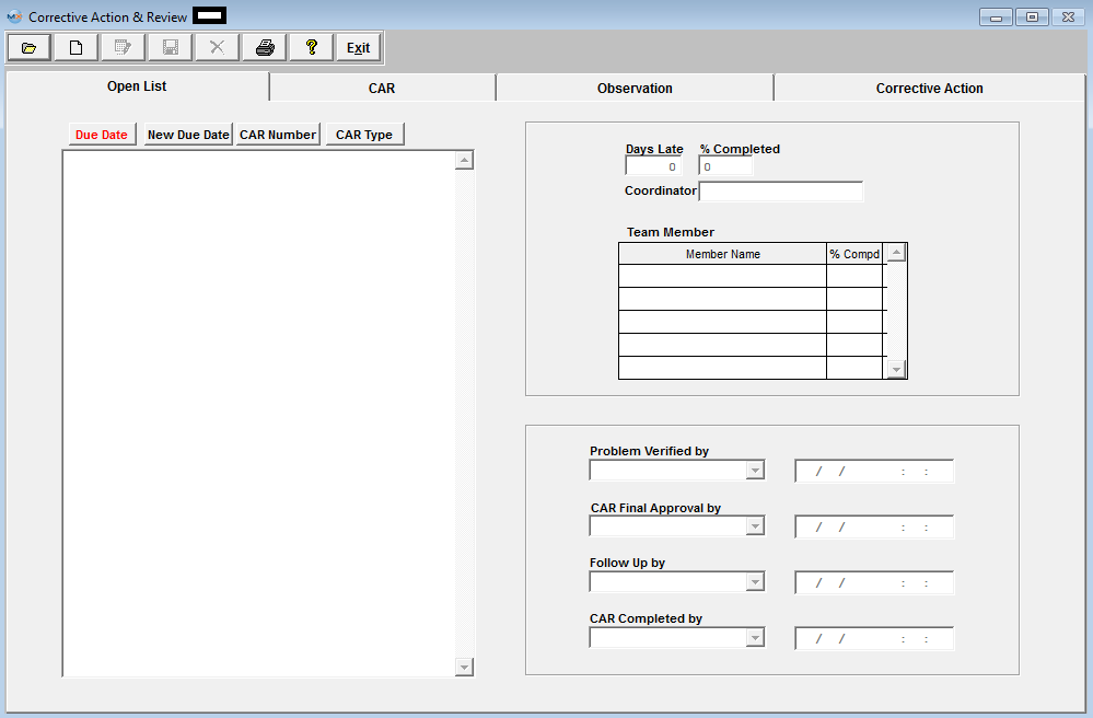 Depress the Find Record action button.
Find by CAR Status
Find by CAR Type
|

| 1.2.4.2. Adding a Corrective Action Record | ||||||||||||||||||||
The following screen will be displayed:
Depress the Add Record action button. The following screen will be displayed:
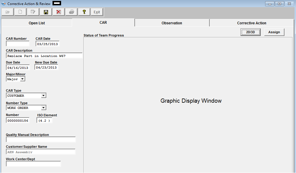
 Enter the CAR Description, Due Date, and New Due Date.
Enter in the Number (Work Order, DMR or RMA) and the ISO element.
Depress the Observation Tab to enter - Description of Condition, Apparent Cause, and Actual Cause information. Within this screen user can also Load a Picture if applicable.
 Depress the Corrective Action tab to enter the Corrective Action and Follow Up and Review information.
Once user has completed adding all the pertain information for the CAR. They may depress the Save button to save the changes or depress the Abandon Changes button to abandon all changes.
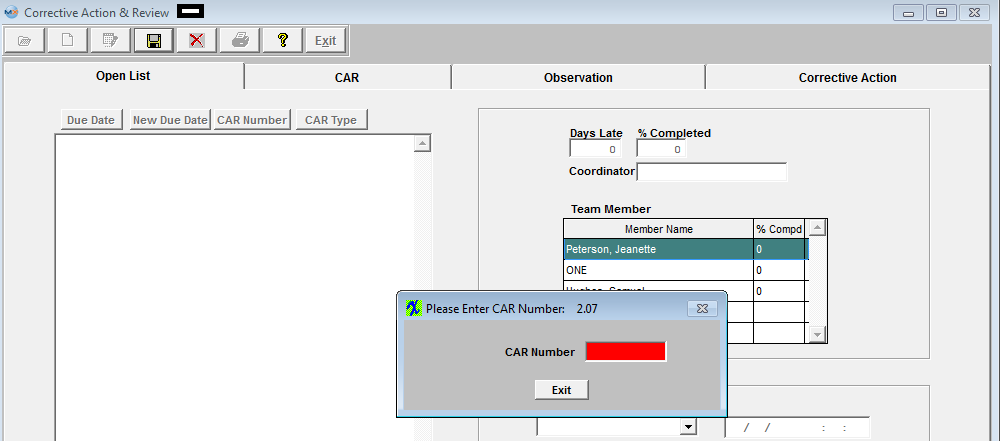
If Set to Manual numbering the following screen will be displayed upon the save to assign a number to the CAR created. If Set to Auto numbering the CAR will be assigned a number upon the save.
 The completed screen should appear as follows:
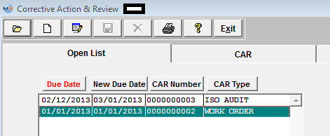
 When entering the CAR module all Open CAR will be displayed listing the Due Date, New Due Date, CAR Number and CAR Type.

To enter a percentage of completion, place the cursor in the % Completion column. Enter in the percentage completed. Depress the Enter key. You will be prompted for the password. The password entered MUST “MATCH” the name of the user.  The user may then depress the CAR tab to view the Team Member Project Status of completion graph.
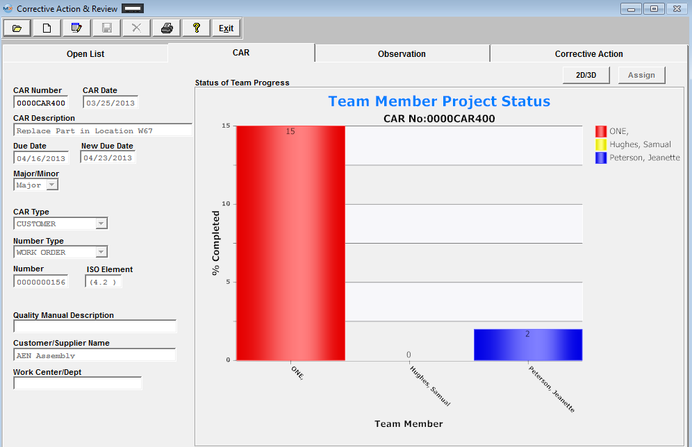 To obtain a 3D version, depress the 2D/3D button.
 |


| 1.2.4.3. Editing a Corrective Action Request Record |
Find the CAR of interest and the following screen will appear:
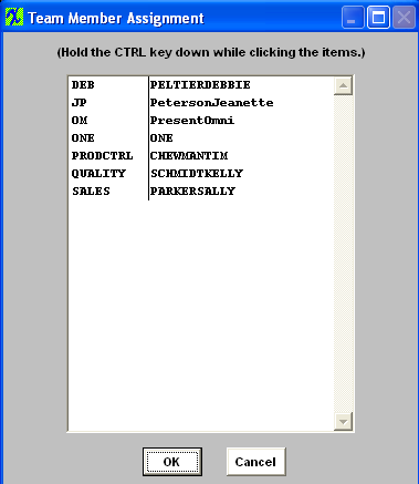
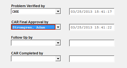
Depress the Edit record and the following fields will become activated on the Open List screen. Depress the down arrow next to each of the desired fields. A list of employees will display for selection. Note: That an entry in the "CAR Completed By" field will Close the record. 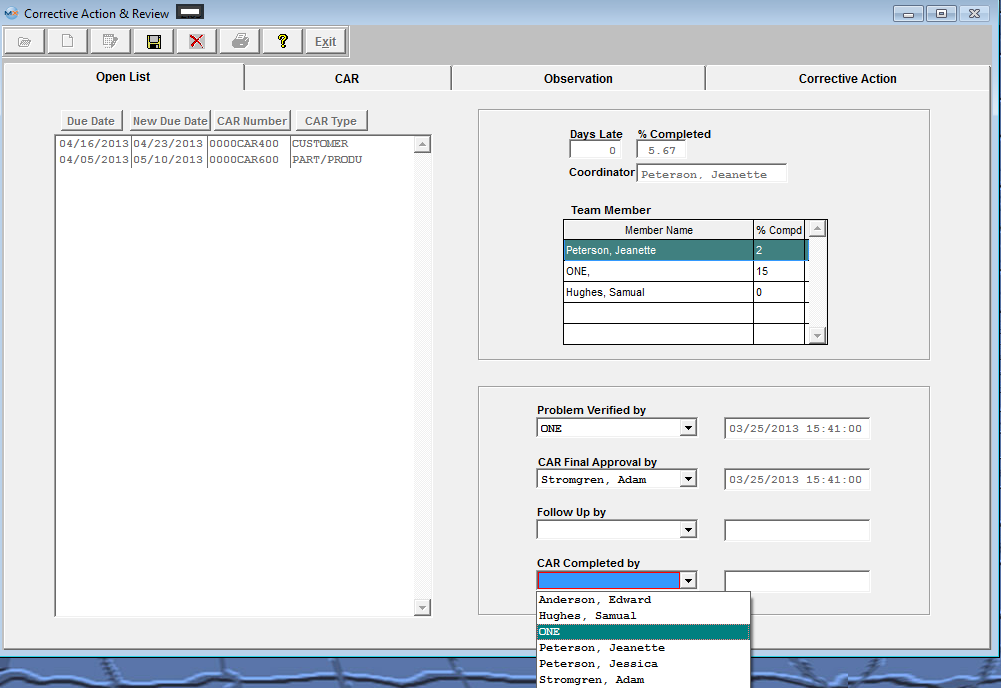 Depress the CAR tab, when in Edit mode all the fields are available for edit.
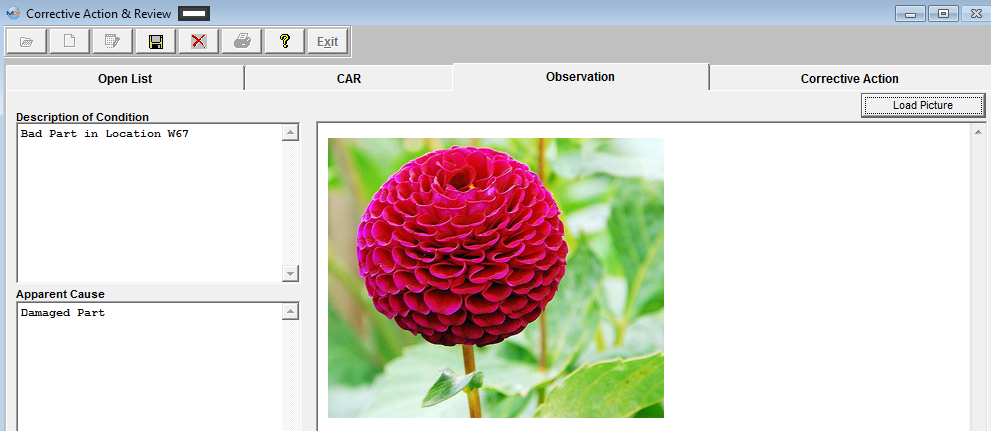
 Depress the Observation tab and all the fields are available for edit. 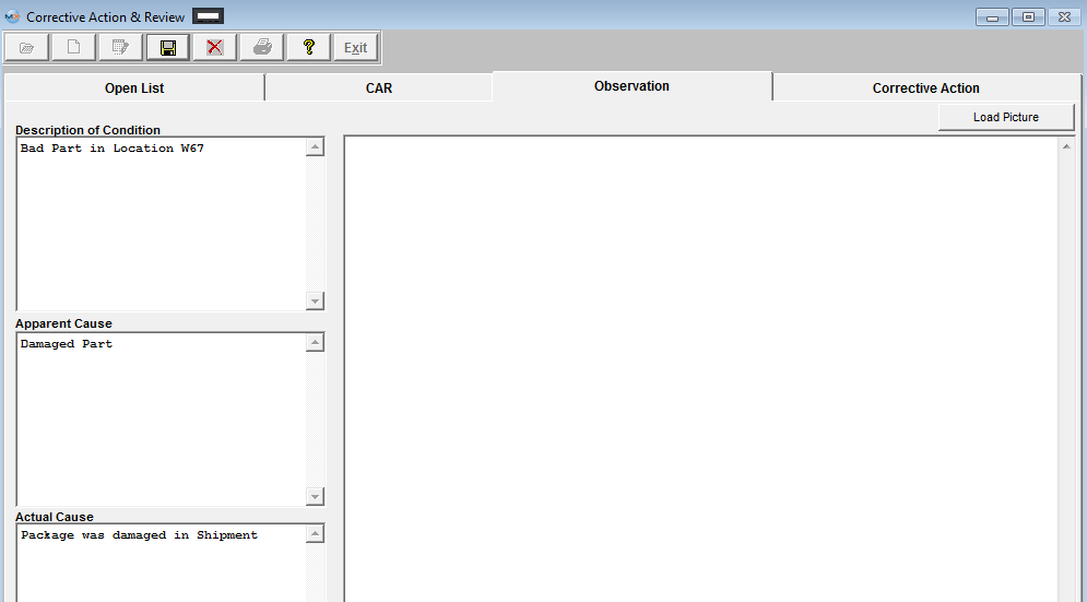 If you wish to load a picture, depress the Load Picture button. The following dialog box will be displayed.
 Select a bit map image/file you want to load by highlighting and double clicking. The load picture will display the image loaded.
 Depress the Corrective Action tab - and enter any Corrective action and/or Follow Up & Review information:
 Once the desired information has been entered into the appropriate locations, depress the Save Button, and enter your password.
|
| 1.2.5. Reports - CAR |
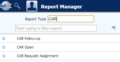
|
To obtain the Corrective Action Reports within the Web, select the WEB Print button from the ManEx action buttons at the top
of the screen. For further detail on How the Reports work within the Web refer
to Article #5477. Note: In order to access the Reports within the
Web the Company Root URL must be setup within the System Appearance module and user must be
linked to web within the System Security Module.
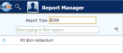
Select the Report Type: BOM - A List of Reports will be displayed that are available on the Web for BOM
NOTE: THESE REPORTS ARE NOT AVAILABLE YET ON ManEx DESKTOP |
| 1.3. Integrated BOM & AVL |
| 1.3.1. Prerequisties for BOM & AVL |
Prerequistes
After activation, "Bill of Material and AVL" access for each user must be setup in the ManEx System Security module. Users with “Supervisor Rights” will automatically have access. Part number for Assembly, Product or Subassembly must exist in the Inventory Control Mgmt module. Part numbers for Components and Subassemblies must exist in the Inventory Control Mgmt module.
Customer Part numbers for Consigned Parts to be added to the BOM must exist in the Inventory Control Mgmt module.
Manufacturer’s Part numbers and Customer’s AVL selections must be setup in the Inventory Control Mgmt module.
Optional Data
Component Costs (Standard, Budgeted or Quoted) for manual calculation of the Standard cost of the Assembly. Note that if the Accounting Module is installed, the cost information must be filled out.
|
| 1.3.2. Introduction for BOM & AVL |
The Integrated Bill of Material and AVL Module allows the user to create, modify, copy, inactivate or delete Bills of Material (BOM’s).BOM’s are the master documents that define what material goes into a product. Item numbers (Product, assembly, subassembly or component) used in BOM’s link the BOM’s to the data that is entered and maintained in the Inventory Control Management- Item Master and Quantity Info screens. Most of the basic data fields (class, type, description, revision, unit of measure, warehouse and order policy) remain the same whenever an item is used in a BOM. Only the data fields that are maintained in the BOM Module, such as the reference designators, kit-to Work Center and quantity per assembly may be changed from one BOM to the next.BOM’s are used to kit components and subassemblies for Work Orders and to drive demand for Material Requirements Planning.
See Article #2560 to view how Inventory, BOM's and AVL's are connected within the ManEx system.
NOTE: If users choose to use effective and obsolete dates in place of proper revision control, you must be absolutely certain that they do not take effect at any point after production begins and before the WO is closed. If this isn't properly managed, you will get the variances. While some may be minor and positive variances may partially offset negative variances, you CANNOT rely on this and you WILL have discrepancies.
The best approach is to always roll the revision when there is a change to an assembly that will affect the value in any way. This becomes even more important if you have WOs open long after the due date and it has had additional changes to the configuration. See Article #5055 for further details.
Definitions
Indented Bill of Material: The Top-down breakdown of the structure of a product. In an indented BOM listing, every subassembly and component is indented one level from the assembly or subassembly into which it goes. Parent and Child Relationships in BOM’s: Each product “parent” has an indented list of “child” components and subassemblies that go into it. Each child item is indented under its parent and may in turn have child components indented under it. Accepted Manufacturer List (AML): The AML is the list of manufacturer part numbers entered in the Inventory Control Mgt.- Quantity Info screen. A manufacturer must first be set up in the Inventory Control Mgt./ Part Manufacturer Setup before its approved part number can be added. Accepted Vendor List (AVL): AVL’s show which manufacturers are approved or qualified for use for a particular customer’s product line or individual product. Only manufacturer part numbers that have been entered in the AML for a particular item can be selected or deleted from the AVL for a customer. A customer’s Approved Vendor List of manufacturers for each internal part is maintained in that customer’s Consigned Inventory record for that part. Consigned Inventory AVL Record: When a Customer part number is assigned in the Inventory Control Mgt.- Customer Reference screen, a Consigned Inventory Record is generated for that item and customer. The Quantity Info screen for the Consigned Customer part number is where the Customer’s AVL is maintained.
Q. Do I have to go into the Inventory Control Management module and assign a customer to the part number? A. Only if the user wants the cross-reference to the customer part number to show for internal parts on the BOM. This field will show up if a BOM Assembly is attached to a specific customer. Anti-AVL: Normally the AVL for each customer applies to all of their product BOM’s. However, if a customer wishes to disqualify a manufacturer from use in one particular BOM, removing a check-mark from the Anti-AVL field may be used to keep the otherwise approved manufacturer from being used on specific BOM’s. Generic and Manufacturer Preferences: A Generic (Genr) manufacturer means that any manufacturer’s part can be used.Generic is generated by the system as the default manufacturer if no other is specified. If specific manufacturers are listed for a part, preferences for use in an Internal or in a Customer’s product may be entered. Preferences are entered in the Inventory Control Mgt.- Quantity Info screen as 1 for 1st, 2 for 2nd, etc. next to the manufacturer. FunctionsBills of Material serves many functions in the manufacturing environment. They are central to all manufacturing operations and are used for everything from product specification to quotation document. BOM’s are key to material requirements planning, kit organization, product structure, and configuration control. Material Requirements Planning (MRP): The BOM is the master plan for building product. An indented BOM from the product top level down to the lowest level component provides the entire material picture for a product. Its quantity and manufacturer preferences are used to kit materials for production to assemble. Its linkage to Item Master Purchase and Production Lead Times and Work Center offsets are used by the MRP to determine which parts to purchase or make and when to provide them. By listing multiple manufacturers and alternate part numbers, the BOM can be used to manage work order shortages. Kitting by Work Center: Selection of a Work Center for each BOM Line Item causes that item to be kitted with other parts for that Work Center. Grouping of the parts needed for the first Work Center helps determine when to start a work order and eliminates the need for sorting out needed parts at each Work Center. Also if parts are not kitted until needed for later work centers, they need not be purchased or made until closer to the time they are actually needed. Production Offset: This time difference between the start of the kit for the first Work Center and the kitting for the Work Center where the part is needed is called Production Offset and can be entered for each line item in the BOM. For example, mechanical parts and chassis parts may not be needed until the work order reaches the final assembly work center. By identifying those parts as Final Assembly parts and entering “x” number of days of Production Offset, the parts will not be scheduled for delivery by the MRP nor need they be kitted for “x” days later than the rest of the Work Order. An entry in this field will displace the due date required by the amount of offset established in the BOM. If the user wanted a part or assembly to be ready on the third week of an order that took 4 weeks, then the user would enter a 3 week offset, and the MRP module would suggest ordering the parts three weeks later than otherwise. Please refer to the Material Requirements Planning Management manual. Engineering Change Control: BOM’s are unique by their revision number and as such are used to control changes to the structure or components in a product. By creating a new Revision level of the BOM with an Effective Date the next day after the Obsolete Date for the old BOM Revision, the user can drive changes in material requirements, kitting and work orders. Or if the new BOM Revision level is to co-exist with the down-rev. Revision, the new BOM is just activated without obsoleting the old BOM. With BOM Revision control, several revisions may exist with different definitions for each. BOM Notes may be used to record Engineering Changes for tracking purposes in the absence of a formal ECO system or documentation. Reference Designators: Unique reference or insertion designations can be assigned in the BOM as guides for placement, assembly, repair or data recording for Statistical Quality Control (SQC).
Note: If the Leveling of Make items is in process then the users will not be able to Add/Edit a BOM, even if the user is already in modification mode of the BOM, the user will not be allowed to save the changes until the leveling process is complete. This is due to the fact that the affected records in leveling of Make Parts is large and complex, the saving time to commit the whole changes to inventory tables does take a large amount of time, so we do not want users making modifications to the BOM when the process is still leveling, so we have added a flag that the users will see within the BOM module.
|
| 1.3.3. Fields & Definitions for BOM & AVL |
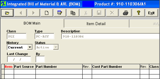
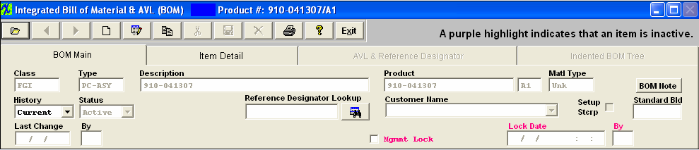
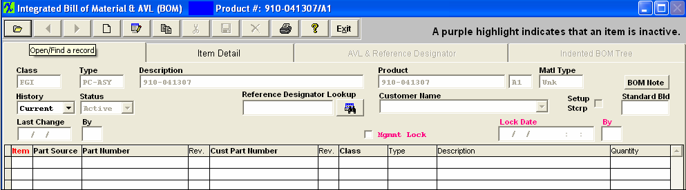
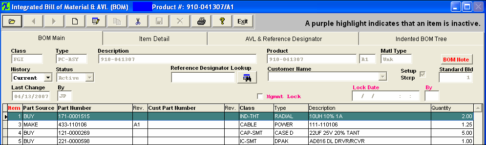
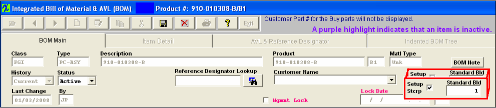
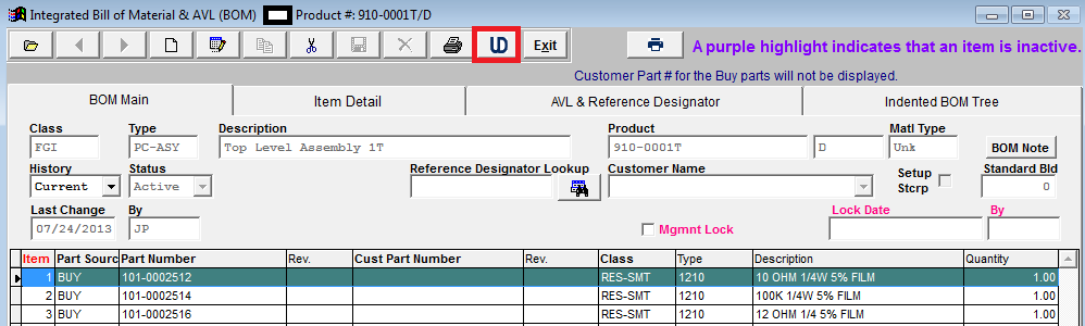
| 1.3.3.1. Bill Of Material Main Screen | |||||||||||||||||||||||||||||||||||||||||||||||||||||||||
This is the screen that appears when opening the module. The product number is displayed in the Bill of Material Module screen header as a reference. The product information will remain on screen while viewing other sections of the BOM module. BOM Main may be used to view, edit, add or delete a Bill of Material. BOM Header information is displayed for any item located after a FIND. If any Line Items have been added to an assembly in the BOM Header, they will be displayed in the Detail Window below. The lines that are inactive will be highlighted in purple. Selection of a Line Item in the Detail Window will cause the other BOM screens to be populated with default and/or added information for that Line Item. Start with this screen to add a new BOM, edit an existing BOM, add a new Line Item or change detail information for existing Line Items. 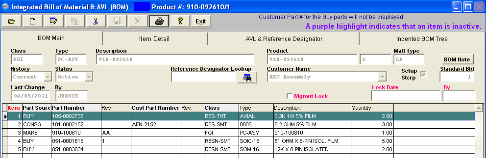 The Header Information fields across the upper half of the screen are populated from the item master and from keyed-in assembly data. The fields in the Body (Detail Window) show information about the components included in the assembly. BOM Main Field Definitions
COMPONENT INFORMATION (Displayed in the Body (Detail Window)
|


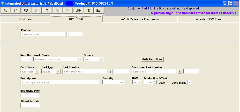
| 1.3.3.2. Item Detail Information Tab | ||||||||||||||||||||||||||||||||||||||
When the user has displayed component parts on the BOM Main screen, and has highlighted one of the parts, pressing on the Item Detail Tab will display information about that component part.
The first row of Header information repeats the assembly Product information. The remaining fields describe Detail information about the component part.
COMPONENT INFORMATION
DIRECTIVE BUTTON The following button is displayed on the BOM Item Detail screen:
|

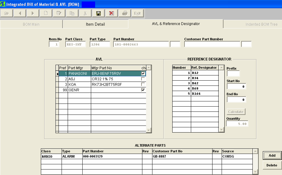
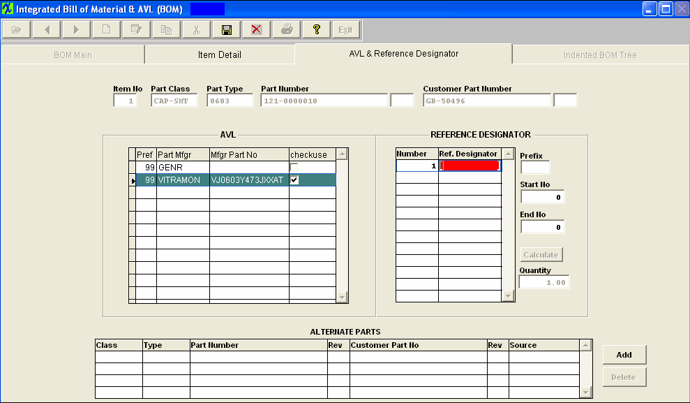
| 1.3.3.3. AVL And Reference Designator Tab | ||||||||||||||||||||||||||||||||||||||||
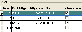
When the user has displayed component parts on the summary screen, and has highlighted one of the parts, pressing on the AVL & REF Tab will display Part Manufacturer and Reference Designation information about the component part.
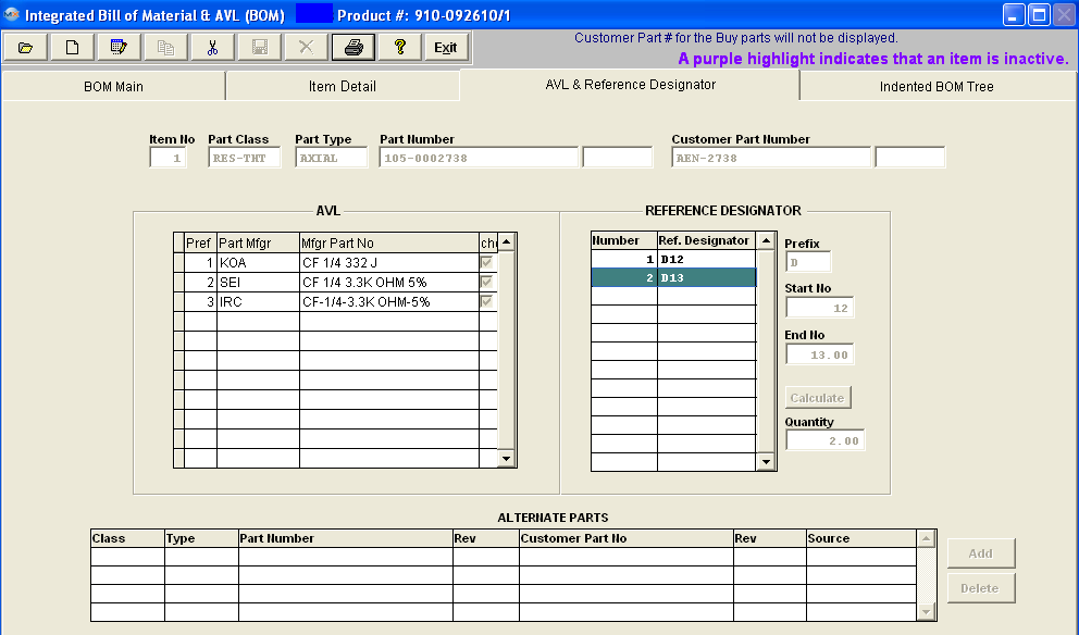
The first row of Information displays the selected detail part information.The Customer Part Number will be displayed if entered in the Item Master. The Left Center portion of the screen displays the Approved Vendors List (AVL). These manufacturers and their part numbers have been selected and designated as approved sources for this particular BOM assembly. When the BOM for the assembly has a customer assigned to it, then Manex will pull the approved AVL's from the customer side NOT the Internal side. If no customer is assigned to the BOM then the AVL’s will be pulled from the internal side. For further detail see Article #2560 . NOTE: If "GENR" is approved on the BOM MRP will consider any inventory for that part even if the AVL is not approved on the BOM.
The left hand column displays the preference order, as assigned in Inventory Control Management.
The right hand column box must be checked for the Kit to issue the part to the Work Order. (At least one AVL must be selected as approved within the BOM module before save will be allowed).
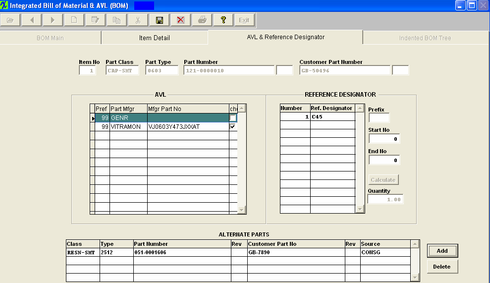
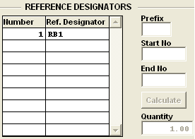
The Right Center portion of the screen displays the reference designators assigned to the component. These fields are optional, but must be completed if reference designator information is to be used in the quality defect collection information. (The ref designators are case sensitive). The bottom portion of the screen is available to list alternate parts that may be used in the absence of the primary part. However, these alternate parts are not listed on kit lists, and are only displayed on this screen. On the BOM, Manex provides a place for users to identify “Alternate Part” for each part called out in the BOM. However, this is for information and cross reference ONLY and there is no connection with the MRP, Purchasing or Kitting, etc. modules. The concept here is that if the engineers want to include alternate (not preferred, and not on AVL) parts for the possibility that in case purchasing can’t get the original parts called for by MRP, they could look up the alternate part on the BOM, and then order that part. However, to get the part into the kit, they will have to add the alternate part as a line shortage to the Work Order, and also check the “ignore shortage” for the part(s) originally required and short on the Work Order. Then MRP will work as needed, and the kit will show the alternate part as a (line) shortage until filled. Incidentally, creating the line shortage and checking the ignore shortage for the original part will result in an MRP directive (the next time it is run) to buy the alternate (line shortage) part. Please refer to the Material Requirements Planning and the Kitting, Allocating & Shortage Management modules. AVL & Ref Designator Field Definitions COMPONENT INFORMATION
The Part Class of the component part. The Part Type of the component part. The component part number. Customer Part Number The customer part number as entered in the Item Master. The Revision number of the customer’s part number. AVL INFORMATION
The order of preference number. An approved manufacturer for the component on the current BOM. NOTE: When the BOM for the assembly has a customer assigned to it, then Manex will pull the approved AVL's from the customer side NOT the Internal side. If no customer is assigned to the BOM then the AVL’s will be pulled from the internal side. For further detail see Article #2560 . The commercial part number. This box must be checked for kitting to pull the component. NOTE: If "GENR" is approved on the BOM MRP will consider any inventory for that part even if the AVL is not approved on the BOM. (At least one AVL must be selected as approved within the BOM module before save will be allowed). REFERENCE DESIGNATOR INFORMATION
The sequential number assigned to each occurrence of the component on the assembly. The assigned location for each occurrence of the part. (The ref designators are case sensitive). If the user wishes to fill in the reference designators automatically, then the start number will be the beginning number in the sequence of reference designators assigned. If the user wishes to fill in the reference designators automatically, then the end number will be the last number in the sequence of reference designators assigned. The quantity of components used in the assembly. ALTERNATE PART INFORMATION These items are the same as previously described. DIRECTIVE BUTTONS
Pressing the Add button in the ALTERNATE area will allow the user to add additional item master part numbers as approved alternates. Pressing the Delete button in the ALTERNATE area will allow the user to remove item master part numbers as approved alternates. |


| 1.3.3.4. Indented BOM Tree Tab |
When the user has displayed component parts on the BOM Main screen, and has highlighted one of the parts, pressing on the Indented BOM Tree tab will display the components with additional information about a make part components.
The first row of data reminds the user of the assembly information.
The bottom portion of the screen displays the components of this assembly. If there is a plus sign to the left of a listed component, click on the plus sign and the components of the listed components will also appear. 
|
| 1.3.4. How To ..... for BOM & AVL |
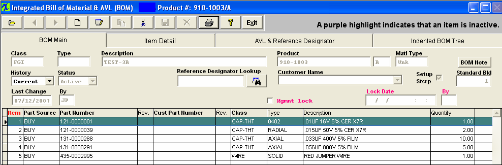
| 1.3.4.1. Find a BOM | ||||||||||
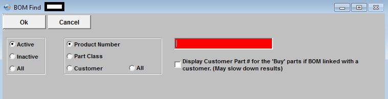
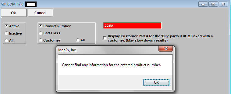
When the screen first opens, the user is limited to only three of the eleven action buttons shown: Find an assembly, run a Report or Exit. Assemblies having Bills of Material will display the components in the Body (Detail Window) below. Selection of one of the components in the window will cause detail information for that item to be displayed if any other BOM screen Tab is selected. Use the Add icon to add components to the BOM of a displayed assembly. Use Edit to change or add Header information. Use the Delete icon to Delete the entire BOM ONLY (See Deletions section). Note: Go to the Item Detail screen to delete only one item from the BOM. Find a Bill of MaterialTo view an existing BOM or to find an existing Make Source Item (Product, Assembly, Subassembly or Phantom) under which to build a BOM.
Click on the Find an existing record Action Button.
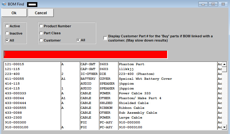
Find an Existing BOM by Product Number
BOM Search Results After finding the Part Number through either the Class Code, Customer, or directly by the Part Number, the BOM Main screen appears, populated with any parts already entered for the BOM of the assembly selected. If no parts have been added to the assembly, the Body (Detail Window) is blank. When BOM is found and displayed the order will be by "Item #". User can re-sort list by clicking on a header that is in Bold that header will display in red. The lines that are inactive will be highlighted in purple. When double clicking on an item, system will take you to the detail page.
User may find a part using the Reference Designator Lookup, by typing a reference designator into the text box it will auto fill the information, when done entering you can press “Enter” or click on the search button next to it and the record pointer in the grid will advance to the part if found.
The Header Information fields across the upper half of the screen are populated from the item master and from keyed-in assembly data. The fields in the Body (Detail Window) show information about the components included in the assembly.
|
| 1.3.4.2. Adding BOM Header Information | ||||||
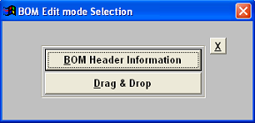
A BOM Header is created by the system when a Make Item is added to the Inventory Control Mgt Item Master and Saved. When the user wishes to create a BOM by adding Line Items to the header, the existing Header is used. The Header identifies the assembly or product and its revision level, shows the status and after creation, allows Viewing BOM components by Current, All, or Selected Effective Dates. Depress the Find button. See Article #571 for Find procedures.
To enter a BOM Note depress the BOM Note button. Depress the Edit button. Enter in the note. Depress the Save button. Depress the Exit button. If you want set up scrap to be considered in Standard Cost calculation, check the Setup Stcrp box. If you want a standard build to be considered in Standard Cost calculation, enter the quantity. See Article 2504 for information on how this affects the Std Cost. Depress the Save button. |


| 1.3.4.3. Adding BOM Line Items & BOM Copy |
Bills of Material may be built up using one of three methods:
|
| 1.3.4.3.1. Drag & Drop Procedure | ||||||||||||||||
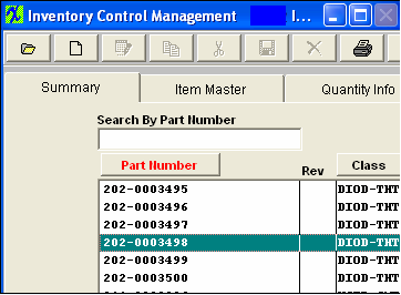
1. Procedure for Drag & Dropping The Drag and Drop Operation allows the user to select components in the Summary screen of Inventory Control Management and drag the items into the Integrated Bill of Material & AVL Main screen to add them as line items in the BOM. Use this procedure as an alternative to Manually Adding Line Items to a BOM. Open the Inventory Control Mgt. Summary screen and use Find to display the desired components.
Size the Inventory Control display by placing the cursor on the far right hand side of the display. Wait until it turns into an arrow. Holding the mouse button down, move it to the left until just the following displays:
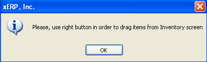
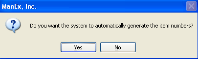
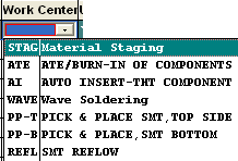
The following selection screen will appear: Choose Drag and Drop. The following message will appear: Move the cursor to the Inventory window. Highlight the desired component. Use the left mouse button to select an item in the Inventory Control Management screen. Release the left mouse button. RIGHT click on the mouse button and CONTINUING TO HOLD THE RIGHT MOUSE BUTTON DOWN, move the mouse cursor over to the BOM screen. Release the right mouse button. Note: When you drop (release the mouse button), be sure that you have the cursor over the white area,. Drag each component into the BOM in Line Item # sequence. Enter the quantity of the part per assembly when prompted. Select the Work Center. Type in the prefix for the Reference Designator. Type in the Reference Designator Start Number. Depress the Calculate button. The Number and Reference Designator Fields will fill in. 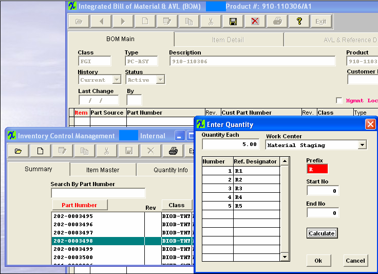 Click on the X button to close the screen. Depress the Save button in the BOM screen when finished dragging and dropping.
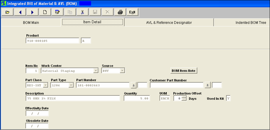
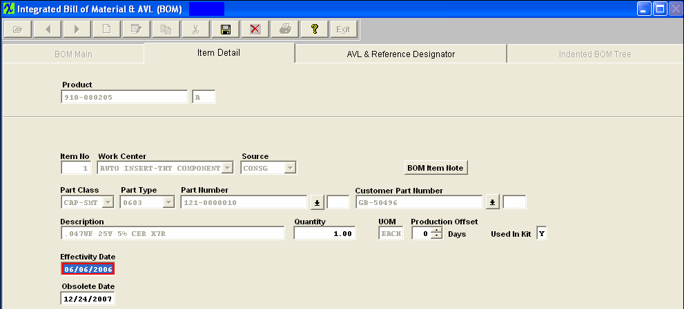
Depress the Item Detail tab in the BOM module. The following screen will appear:
Review the detail. If you want to make any changes, depress the Edit button while this screen is open. Type in your password. You may change Item Number, Work Center, Quantity, Production Offset days, Used in Kit, and may add Effectivity Date and Obsolete Date. Depress the Save button. All the AVL's will default in as approved and require the user to deselect as desired. If no AVL's are approved a popup will appear forcing the user to approve at least one AVL.
When the BOM for the assembly has a customer assigned to it, then ManEx will pull the approved AVL's from the customer side NOT the internal side. For example: Part “XYZ” may have several AVL’s and several different customers linked to it. Each customer may approve different AVL’s. So when the part is linked to a specific customer’s BOM only the AVL’s linked to that customer part will be displayed on the BOM as approved. The AVL screen looks at the accepted AVL’s for that customer on the “consigned” or “Customer” side of each part whether it was added to the BOM as a “BUY”, “MAKE” or “Consigned”. If no customer is assigned to the BOM then the AVL’s will be pulled from the internal side. NOTE: If "GENR" is approved on the BOM MRP will consider any inventory for that part even if the AVL is NOT approved on the BOM. For further detail refer to Article #2560 . If you want to add alternate parts, depress the AVL and Reference Designator tab. Depress the Edit button. Enter your password. Depress the Add button next to the alternate parts section of the screen.
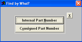
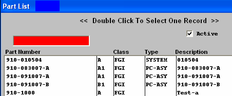
If you select Internal Part Number, a list of all Internal part numbers will appear: Type the internal part number in the red box or highlight and double click to select.
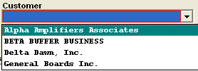
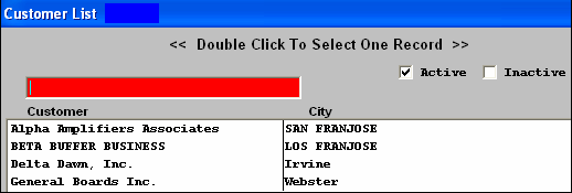
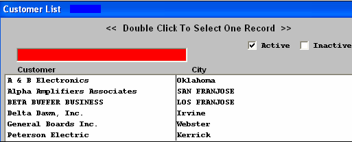
If you select Consigned Part Number, a Customer List will appear: Type the customer into the red box or highlight and double click
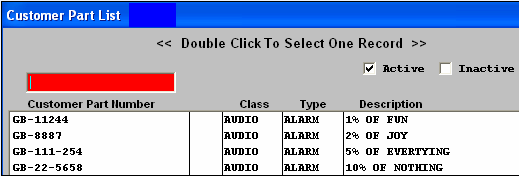
A list of all of that customers parts will appear: Type in the customer part number or highlight the item and double click to access. : Information regarding the alternate part will display in the bottom section, as displayed below
Depress the Save button. |
| 1.3.4.3.2. Manual Entry | ||||||||||||||||||||
Procedure for Manually Adding Line ItemsUse this procedure as an alternative to Drag and Dropping from the Inventory Summary screen. Open the Integrated Bill of Material & AVL BOM Main screen and Find desired Header.
To add a component, click on the Add Record button, enter password.
The item detail screen will appear:
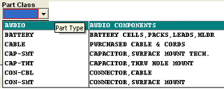
Then select Source (Make, Buy, Consigned or Phantom), from the drop down menu: When building a BOM and you enter the source as a “Phantom”, then when entering the part number that is a “Make/Phantom”, the source changes to a Make” part. The reason the source field shows at all is to limit the number of part numbers that are available to choose from. But you can enter any valid part number and the source will change to the source of the part number entered. So, yes, the source of the sub-assemblies will show as a “Make” part, even though they are actually “Make/Phantom” parts. The details of the BOM will also show they are “Make/Phantoms”. We allow nested phantoms, of either the “PHANTOM” or the “Make/Phantom” variety. In kitting, we have the code to blow down through the first level of make/phantoms, so that the parts included in the first sub-assembly level down are listed as kit requirements. We have extended this further so that if there are Make/Phantom parts in the first sub-assembly level, those also break down to the components in the second sub-assembly level. This process extends as long as there are “Make/Phantoms” in the indented BOM. Either enter the item number by typing it directly into the Part Number field or select Part Class and Part Type, as illustrated below:
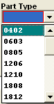
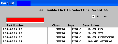
Select the Part Class. Select the Part Type. Depress the down arrow next to the Part Number box. A list of all of the inventory parts within the selected Class and Type will appear. Type the Part Number into the Red box or highlight and double click to select. If the item is a Consigned Item, enter either the Customer part number OR the Internal Part number, in the respective fields If you added an internal part and if there is a matching Customer part number in the Inventory Customer screen, it will automatically appear as soon as the internal inventory part is selected. Conversely, if you typed in a customer part number, the internal part number information will automatically appear. Enter the Quantity of the item required for each assembly produced. (Note: Extra parts for setup or run losses should be added in the Inventory Control Mgt. Item Master Run Scrap % or Setup Scrap Qty. field, not in the Bill of Material.) Enter the production offset days by toggling on the up and down buttons. If the component is to be pulled in the kit, leave the Y in the Kit box.If not, remove it. Enter the effectivity and obsolete dates, if desired.
Depress the AVL & Reference Designator tab
All the AVL's will default in as approved and require the user to deselect as desired. If no AVL's are approved a popup will appear forcing the user to approve at least one AVL.
When the BOM for the assembly has a customer assigned to it, then ManEx will pull the approved AVL's from the customer side NOT the internal side. For example: Part “XYZ” may have several AVL’s and several different customers linked to it. Each customer may approve different AVL’s. So when the part is linked to a specific customer’s BOM only the AVL’s linked to that customer part will be displayed on the BOM as approved. The AVL screen looks at the accepted AVL’s for that customer on the “consigned” or “Customer” side of each part whether it was added to the BOM as a “BUY”, “MAKE” or “Consigned”. If no customer is assigned to the BOM then the AVL’s will be pulled from the internal side. NOTE: If "GENR" is approved on the BOM MRP will consider any inventory for that part even if the AVL is NOT approved on the BOM. For further detail refer to Article #2560 . Enter the Ref designators manually in the table or enter the prefix letter, Start No and End No and depress the Calculate button to auto-number.
If you want to add alternate parts, depress the AVL and Reference Designator tab. Depress the Add button next to the alternate parts section of the screen.
If you select Internal Part Number, a list of all Internal part numbers will appear: Type the internal part number in the red box or highlight and double click to select.
If you select Consigned Part Number, a Customer List will appear: Type the customer into the red box or highlight and double click
A list of all of that customers parts will appear: Type in the customer part number or highlight the item and double click to access. : Information regarding the alternate part will display in the bottom section, as displayed below.
Once user has completed entering all information for line item number, depress the Save button.
|

| 1.3.4.3.3. Copy an Existing BOM | ||
Procedure for Copying from an Existing BOM A new assembly may have a BOM applied to it by copying the bill of material from an existing assembly. To simplify changing a Bill of Material, while maintaining the original version of the assembly, users can copy the parts list into a new assembly and make changes as needed.
Depress the Copy button and enter the user’s password will prompt the user for the existing bill of materials from which to copy the components. The user may find the existing assembly from which to copy either by part number or by part class.
MANEX will populate the new assembly with all of the part information from the existing assembly, except for parts belonging to a customer. Those items will have to be added manually. The filled in BOM is displayed below:
Depress the Edit button to add the customer name and any other needed changes, in any of the screens. The user can then either Save the new assembly with all of the components, or Cancel the operation. Approved AVL's will be retained when copying BOM's except for one exception: Buy part has 3 AVL's and customer A is associated with buy part and also has 3 AVL's, Create BOM for Customer A add buy part all 3 AVL's will be listed, approved only one of the AVL's on BOM A. Create new product changing Rev. to B. Copy BOM A to B. (BOM B has no customer assigned). All AVL's will copy over and all will be checked. |
| 1.3.4.4. Bill Of Material Deletions |
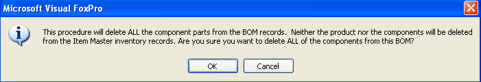
The Delete button takes on dual meanings. If the user is in the BOM Main Tab when the button is pushed, the button will delete ALL items on the BOM. You will be prompted for your password. The following message will appear:
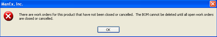
If there are open work orders for the assembly, then the user is presented with a prompt advising that the bom cannot be deleted while open orders exist, as displayed below:
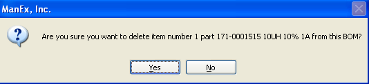
If the user is in the Item Detail Information Tab when the button is pushed, the button will delete only the item highlighted. You will be prompted for your password. The following message will appear:
|
| 1.3.4.5. Procedure For Editing Line Item Details |
Use this procedure to edit Line Item details after entering BOM Header information and Line Item Part Numbers and Quantities per assembly manually, using drag and drop, or copying. Click on the Item Detail tab. Depress the Edit button and enter password. 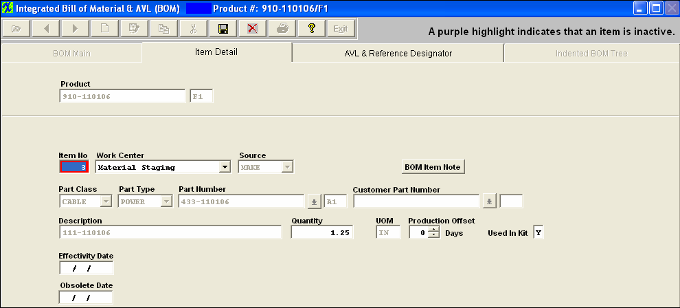 NOTE: If users choose to use effective and obsolete dates in place of proper revision control, you must be absolutely certain that they do not take effect at any point after production begins and before the WO is closed. If this isn't properly managed, you will get the variances. While some may be minor and positive variances may partially offset negative variances, you CANNOT rely on this and you WILL have discrepancies.
The best approach is to always roll the revision when there is a change to an assembly that will affect the value in any way. This becomes even more important if you have WOs open long after the due date and it has had additional changes to the configuration. See Article #5055 for further detail.
The Item number, Work Center, Qty, Production Offset, Used in Kit, Effective Date, and Obsolete Date can be edited on this screen. The Production Offset would be edited, If an item is to be kitted to a Work Center that will not be reached by the Work Order until X days later, enter X days in the Production Offset to allow kitting to that Center X days later. NOTE: This will affect the MRP demands until the kit status has been changed to "KIT IN PROCESS". Once the kit status has been changed to "Kit in Process" the parts now become a kit shortage, and the system will calculate from the WO due date or production lead time and NOT from the production offset. Enter Effectivity Date for the line item to be used in the BOM. (Note: Prior to Effectivity Date or after Obsolete Date, the line item will not appear on the Current BOM view nor will it appear on a Pick List to Kit the Assembly.) Edit the "Used in Kit" by selecting Y (Yes) for Used in Kit unless the item is not to be issued when a kit is pulled. Select P (Phantom) to cause a Make subassembly to be treated as a Phantom when kitted. Select N (No) if the item is provided to the Line by some other means than kitting. (Note: Chemicals and adhesives are typical not-kitted items that are referenced on the BOM for costing or specification but issued to the production floor on a bulk replenishment basis.) If you depress the AVL & Reference Designator tab the Ref designators can be edited manually in the table OR Enter the Prefix letter, Start No and End No and click on the Calculate button to auto-number. Here is where you will also check the approved AVL's and uncheck the AVL's that are NOT approved for this BOM. NOTE: If "GENR" is approved on the BOM MRP will consider any inventory for that part even if the AVL is NOT approved on the BOM. When adding new AVL's to the item master, if you do not want the BOM's automatically updated be sure that the "Disable Automatic BOM AVL update" is Enabled. See article #1477 for more information. You may also Add or Delete Alternate Parts by depressing the Add or Delete button near the Alternate Parts to select alternative part numbers for the Line Item currently being edited in the BOM. This table is in the BOM screen because alternate part usage is always dependent upon the application and hence is BOM specific. (Note: Use the Quantity Info screen and AVL window to show alternate manufacturers; the alternate part window is only for items with a different internal part number (such as faster or tighter tolerance parts) that can be used on a temporary deviation when there is no choice.) Once you have completed the changes, depress the Save button and BOM will be updated.
Note: If the Leveling of Make items is in process then the users will not be able to Add/Edit a BOM, even if the user is already in modifucation mode of the BOM, the user will not be allowed to save the changes until the leveling process is complete. This is due to the fact that the affected records in leveling of Make Parts is large and complex, the saving time to commit the whole changes to inventory tables does take a large amount of time, so we do not want users making modifications to the BOM when the process is still leveling, so we have added a flag that the users will see within the BOM module.
|
| 1.3.4.6. Bill of Material (BOM) Used in Kit Option and how it affects Kitting & MRP |
Within the Bill of Material module the users have the option to mark each item loaded to the BOM as Used in Kit Y, N or F. Y = Yes, this part is used in the Kit and will be considered fro MRP demands and appear within the Kitting module Qty Pick screen. Once the parts have been issued to the kit the system will automatically decrement it from inventory upon WO complete. N = No, this part is NOT used in the kit, but it will be considered by MRP for demands but will NOT appear in the Kit module Qty Pick screen. This item will still be displayed on the Kit Pick Worksheet but it will have the “N” next to the item so users will know that it is not used in the kit. Example: you would use this option for Documentation. NOTE: Keep in mind that this item will be picked by the users on the floor but it will not be relieved from inventory in any way through the Kitting module. Users have to go make and manually adjust the inventory qty’s for this type of item.
MRP includes items with "N" flag in "used in kit" for Purchase Order Actions. The flag does not mean don't buy it, but instead, it means don't kit it. The part is still needed, or it wouldn't be on the BOM. Or the quantity would be zero. This feature is usually used by Users who have bulk stock on the floor, and the assemblers pull the parts out of floor stock. But there still remains the requirement to get the parts in house so they can be put into floor stock. F = Floor, this would be used for an item that is not kept in the Stock room but is physically stored out on the Floor in production. “F” items will also be considered by MRP for demands, but will NOT be displayed on Kit Module Qty Pick Screen or the Shortage report. This item will still be displayed on the Kit Pick Worksheet but it will have the “F” next to the item to indicate to the users that it is located on the Floor. NOTE: Keep in mind that this item will be picked by the users on the floor but it will not be relieved from inventory in any way through the Kitting module. Users have to go make and manually adjust the inventory qty’s for this type of item.
|
| 1.3.4.7. Bill of Material Setup Scrap Checkbox |
Within the Bill of Material Module you will see a Setup Scrap check box and a Standard Build field. If you wish for the setup scrap qty’s to be included in the Kitting and MRP calculations, Standard Cost Adjustments, etc. . . you need to make sure that the BOM has the Setup Scrp box marked. Then upon checking this box the system will default in the Standard Build qty to 1 (just because it can not be blank) It is recommend that you change the Standard Build qty to the desired average build qty for the product (the Standard Build will affect how the system will calculate Standard Cost Adjustments, etc. . . within the system)
|
| 1.3.4.8. Make a Obsolete Part Available on a BOM |
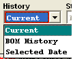
Find an existing BOM
 Depress the pulldown next to the History and Select BOM History, all parts will be displayed, including the parts that have been obsoleted.
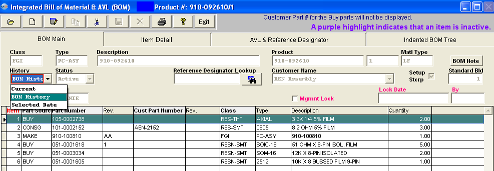 Highlight the part that has been obsoleted and enter the item detail screen, depress the edit button and remove the obsolete date or change it to a later date.
 Now the part is available to use.
 |
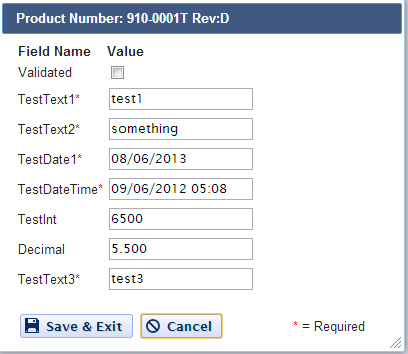
| 1.3.4.9. Link User Defined Fields to a BOM |
| The User Defined fields MUST be setup within Web ManEx. For further detail see Article #5454.
The User Defined Fields can
then be linked to a Bill of Material by selecting a record in the ManEx
Desktop, and selecting the UD action button (as displayed below).
The UDF for that section will then be displayed, and user can make changes (if applicable), Save & Exit or Cancel.
|
| 1.3.5. Reports - BOM & AVL | ||||||||||||||
To display or print a Report for a BOM, first find the BOM. (See Article #4795).
To obtain the Bill of Material Reports within the Web, select the WEB Print button from the ManEx action buttons at the top of the screen. For further detail on How the Reports work within the Web refer to Article #5477. (Note: The only BOM Report available on the WEB right now is the PO BOM Addendum) Note: In order to access the Reports within the Web the Company Root URL must be setup within the System Appearance module and user must be linked to web within the System Security Module. Select
the Report Type: BOM - A List of Reports will be displayed that are
available on the Web for BOM
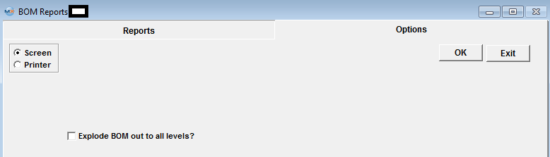
To obtain the Bill of Material Reports within the desktop, select the Print button from the ManEx action buttons at the top of the screen.
The
following reports screen will display a list of reports that are available on
the ManEx Desktop:
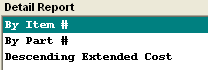
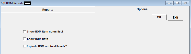
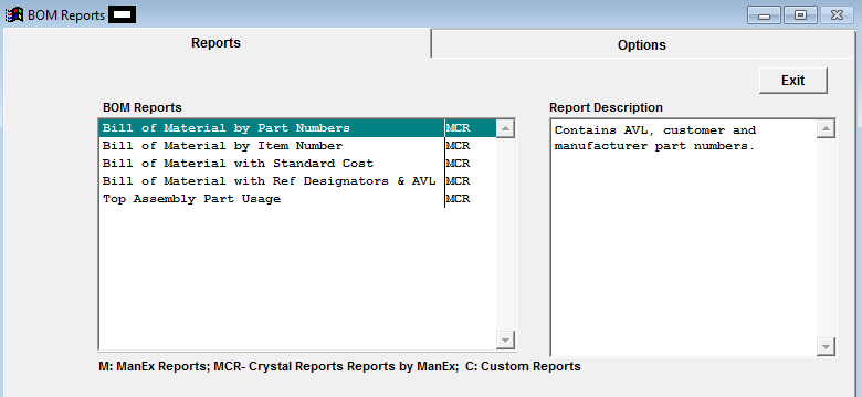 Highlight the report desired and click on the Option tab. (The BOM reports will indicate in the Source column if the item is setup as Make/Buy or Make/Phantom, along with Consigned or Buy).
BILL OF MATERIAL by Part Numbers
Depress the OK button.
The BOM displayed on screen will print as follows. (The two PN's boxed in Red are parts that have been exploded out for Sub-Assembiles)

BILL OF MATERIAL BY ITEM NUMBERS
Depress the OK button.
The BOM displayed on screen will print as follows: (The parts in the Red boxes are parts that have been exploded out) 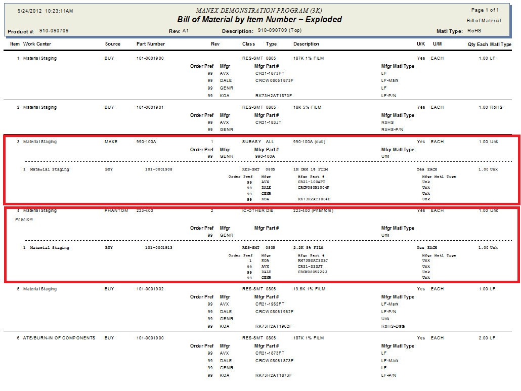
BILL OF MATERIAL WITH STANDARD COST
Note: This report takes into consideration the Std Bld Qty when calculating the setup scrap. You might find the cost calculated in SFT is different from the calculation shown on this report due to, that if the part UOM is "EACH" and the part has scrap % the code will round it up to next inter number.
a) For the PHANTOM parts in this report the standard cost calculated is based on their components (SUM of component's qty * component standard cost). Once the standard cost is calculated for the PHANTOM part, the report will treat the PHANTOM part as a single entity on the top assembly BOM and proceed as it was a BUY part with the std cost already entered.
b) If one of the component parts is a MAKE (not MAKE_BUY) and HAVE components assigned to it, the report will NOT show std cost of the parts itself, it will only show std cost of its subcomponents.
c) If one of the component parts is a MAKE (not MAKE_BUY) and does NOT HAVE parts assigned to it the report will show std cost of the part itself. d) If one of the component part is a MAKE and MAKE_BUY the report will show price for the part itself and will show 0.00 costs for the subcomponents.
e) If one of the component part is a MAKE and a Phantom/Make the report will NOT display the std price for this part because the report will show the cost of this parts components.
Note: This report will only display the costs for ACTIVE parts and subassemblies as of the date of the report and will NOT include any parts that may have been identified as inactive either in the item master or in the obsolete date of the part on the BOM.
The values displayed should be in sync with the Cost Roll Up values. The following may be why the Standard Cost Roll is different from the Cost BOM Reports.
a) On the costed BOM Report for a Make/Buy assembly we display the value of the BOM in the costed report, but that total is NOT used in subsequent rollups to higher levels only the standard cost is. b) In Kit Default Setup , user can "Exclude Scrap and Setup Scrap" in Kitting, MRP, and Cost Rollup, and this will override the "Setup Stcrp" box in the BOM. Therefore, if user checks "Setup Stcrp" checkbox along with a Standard Bld qty in BOM header, but has the checkbox checked in Kit Default Setup to "Exclude Scrap and Setup Scrap" for Cost Roll, the Cost Roll will NOT calculate the Setup Scrap cost, but this report will always calculate the Setup Scrap cost and this will cause unfavorable Configuration Variances. For further detail on how Excluding Scrap and Setup Scrap values will affect the variances see Articles #3067, #3053, and #3320 .
The BOM displayed on screen will print as follows: This report ALWAYS includes ALL the parts (including the items flagged as "N" for Used in kit) 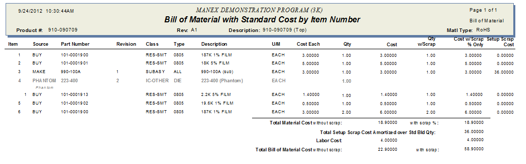
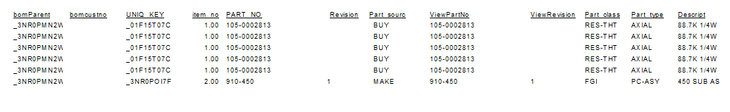
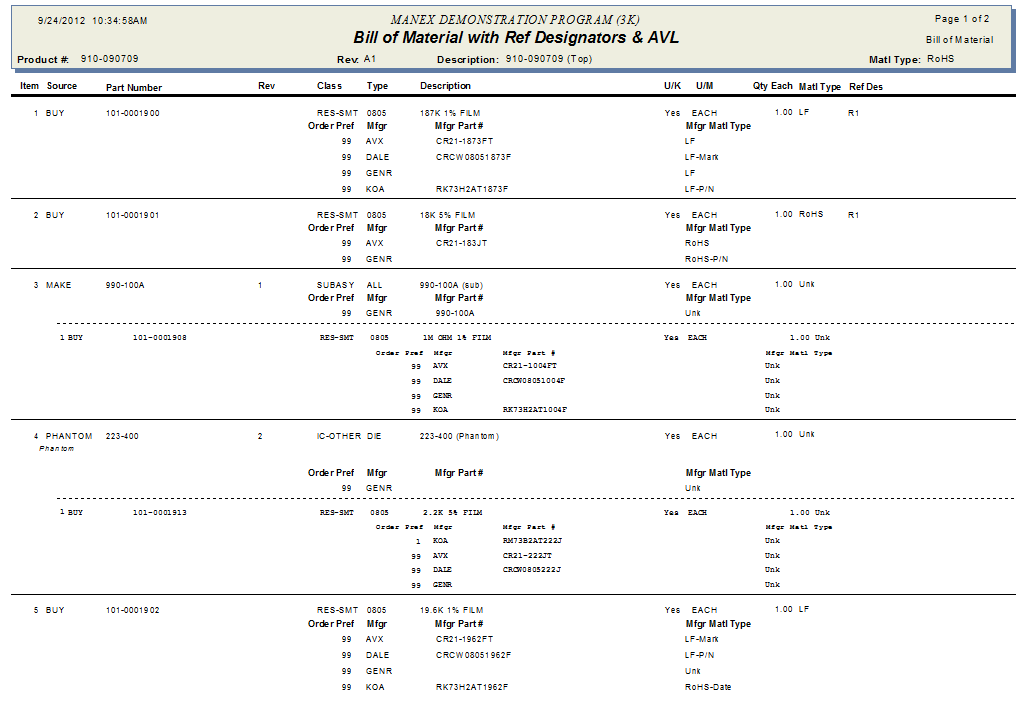
BILL OF MATERIALS WITH REFERENCE DESIGNATORS & AVL
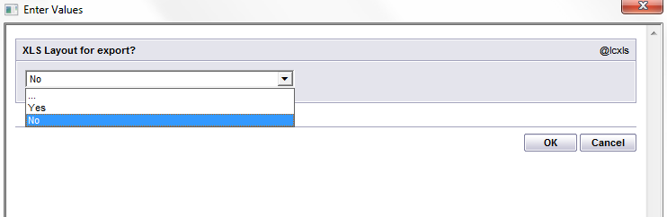
If the user selects 'YES' the display will show as follows. Keep in mind not all of the field could be displayed on this page size, but upon export all fields will be displayed.
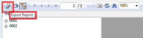
 Select the Export option
 The followng screen will be displayed, Select format 'Excel - Data only' 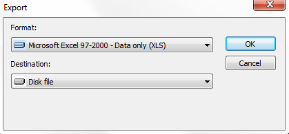 The following screen will be displayed, within the option section be sure to select to include the Header Info 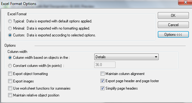 Select file name and destination
 XLS results should look very similar to the VFP XLS dumps we have as displayed below
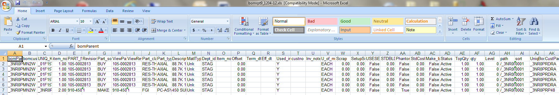 If user selects "No' to export report to XLS file The BOM displayed on screen will print as follows:
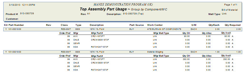
TOP ASSEMBLY PART USAGE
The following report is printed:
|

| 1.3.6. FAQs - BOM & AVL |
| Facts and Questions for the Bill of Material (BOM) Module |
| 1.4. BOM Import |
| The BOM Import module is available in the WebManEx. For further detail see Article 5326 |
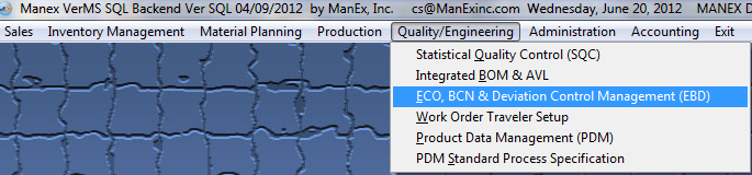
| 1.5. ECO, BCN & Deviation Control Management (EBD) (OPTIONAL Module) |
| 1.5.1. Prerequisites - EBD |
ManEx’s standard module configuration allows most users to accomplish their daily tasks. For those users wanting to get more from ManEx by leveraging the total solutions, this is one of the optional modules available for purchase. To place an order or to learn more about this specific module or any of the other optional modules please contact us at http://manex.com\contactus.aspx After activation, "Engineering Change Order" access for each user must be setup in the ManEx System Security module. Users with “Supervisor Rights” will automatically have access.
The product to be revised must be setup in the Inventory Control Mgmt. Any new parts to be added must exist in the Inventory Control Mgmt. A Bill of Materials must exist for the product being revised. |
| 1.5.2. Introduction - EBD |
This module allows users to document the source (internal or customer), the purpose, the details, and the impact of the change. The module can apply the changes to new and existing jobs, and ensure that production is aware of the change and is using the latest information.
This module allows users to document the changes using one of the following three approaches: "ECO" = An ECO records Engineering changes for assemblies when there is a Revision or Part Number change. There can be changes to the Bill of Materials components and/or quantity, to the materials cost, labor cost, whether or not there is a serial number required and to the description. The user can enter whether existing WIP or FGI items are to be scrapped or modified. Once all of the engineering changes are entered, the ECO needs to be approved by the the approvals (as specified in the ECO setup module). Once the approvals are entered, the user may Update the following records: Inventory Master, Product Routing, Product Data Management and Bill of Materials.NOTE: These records will ONLY be updated if the Revision or Part Number has been changed. "DEVIATION" = A Deviation creates a record that someone approved the change in the process for individual work order(s). Such as using a different part, leaving a part off, or perform a special additional step in the process, etc. When a Deviation is created within this module no records are updated or changed. It is a document for reference only. The user may print the deviation and it will list the work orders selected to be updated. Deviations have an expiration date so users will know that their customer or management allowed the modification for a limited period of time.
"BCN" = When "BCN" type is selected, the user can change all part information just like ECO, but user won't be able to create a new product number/rev, or click any "copy" checkboxes on "Update/Create records" page. WO and SO lists will also not be available for selections. When the "Update All Records" button is clicked, the BOM of the product number will be updated just as if the BOM was changed in BOM module. This feature will track any changes to the BOM through the system. |
| 1.5.3. Fields & Definitions - EBD |
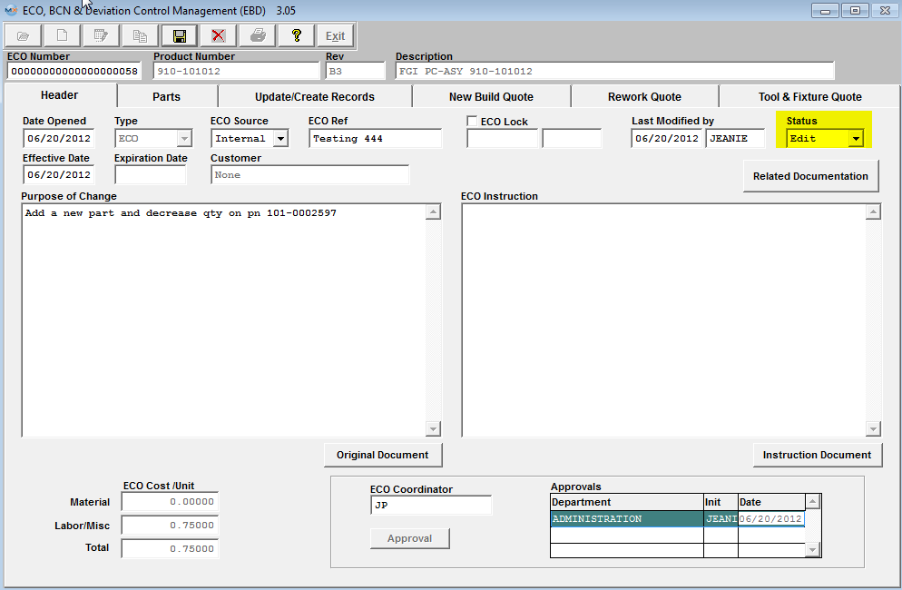
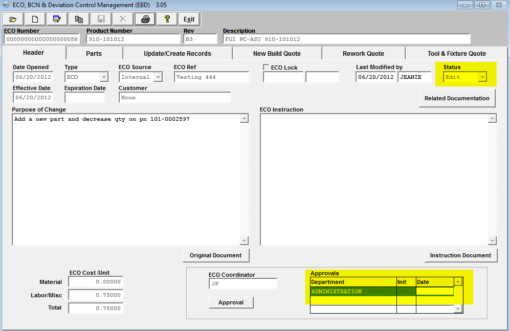
| 1.5.3.1. Header Tab | |||||||||||||||||||||||||||||||||||||||||||||||
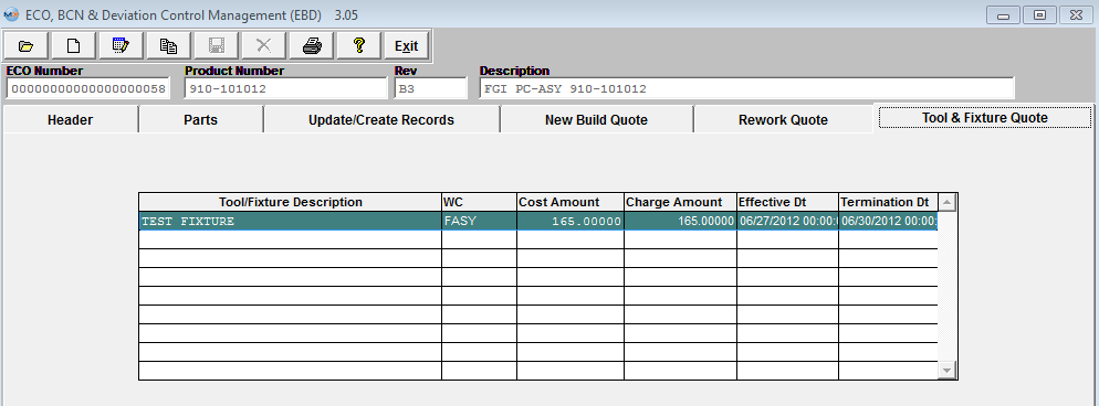
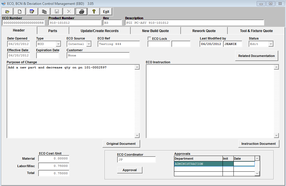 Header Tab Field Definitions
|
| 1.5.3.2. Parts Tab | ||||||||||||||||||||||||||||||||||||||||||||||||||||||||||||||||||
|
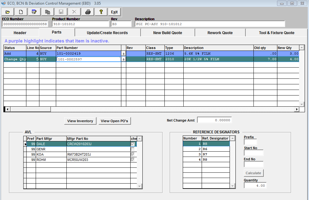 Parts Tab Field Definitions - The Parts tab displays any additional changes or deletions of Bill of Material Components. If the part added has a status of "Inactive" within the Inventory Control Management, it will be highlighted in purple as an indicator to the user that this item is inactive at this time. If the user chooses to leave the inactive part on the ECO, that part number record status will automatically be changed to Active upon the "Update Records" button being depressed, so user will not have inactive parts listed on the BOM. The user will receive a warning that an XLS file has been created for reivew.
|
| 1.5.3.3. Update/Create Records Tab | ||||||||||||||||||||||||||||||||
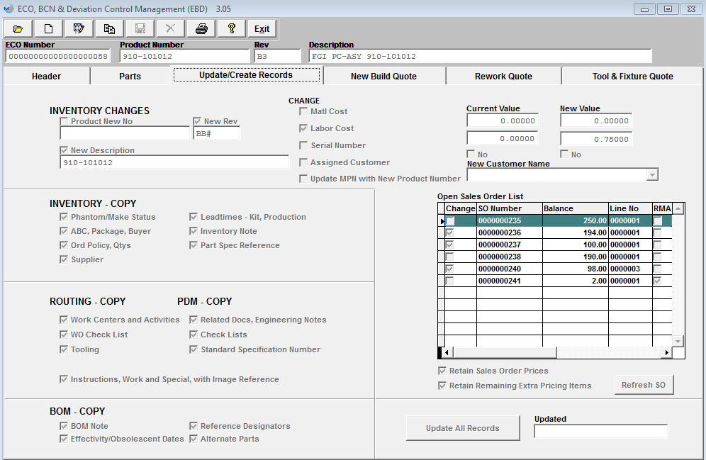 Update/Create Records Tab Field Definitions - This tab displays the revised product number, description, changes in Standard Cost, Labor Cost, whether serial number is required and updates for Engineering Change Orders only. Note: This tab is not available for Deviations or BCN. Inventory Changes section:
Change section:
The rest of this screen comes up with all of the boxes checked for copying the revisions into the Inventory Master, Production Routing, Product Data Management and Bill of Materials. If the user does not want the assembly copied, the box will be unchecked. |

| 1.5.3.4. New Build Quote Tab | ||||||||||
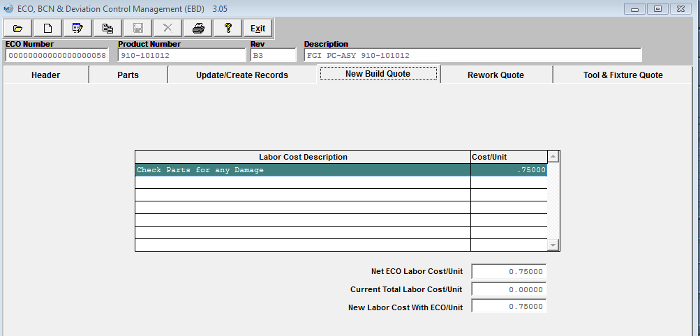 New Build Quote Tab Field Defintions - This tab desplays Labor Costs associated with the build of the new product number and revision and calculates the New labor Cost associated with each new unit.
|
| 1.5.3.5. Rework Quote Tab | ||||||||||||||||||||||||||||||||||||||||||||||||
 Rework Quote tab Field Definitions - The Rework Quote tab details any Rework Costs due to reworking the existing quantity in Work In Process and/or Finished Goods Inventory. Open Work Order List (As of ECO Open Date) window: Note: The value of the "as of" is that it can affect the quote pricing and allows customers to better get that information.
Rework Cost Description window:
Inventory Locations (As of ECO Open Date) window: Note: The value of the "as of" is that it can affect the quote pricing and allows customers to better get that information.
The window at the bottom right hand side of the tab will display the total costs associated with the rework. Note that these costs DO NOT forward into either the Inventory Control Item Master nor the Accounting records.They are not associated with any new products which will be manufactured after the update to the latest revision, but pertain only to the costs associated with reworking either existing WIP or Finished Goods. Totals (As of ECO Open Date): Note: The value of the "as of" is that it can affect the quote pricing and allows customers to better get that information
Units to Rework:
Cost to Rework:
|


| 1.5.3.6. Tool & Fixture Quote | ||||||||||||
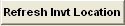
 Tool & Fixture Quote Field Definitions - Once the ECO record has been approved and updated within the system. This Tool/Fixture information will then be carried forward into the PDM and Routing Setup modules.
This is the description information loaded from the System setup/Tooling Setup for selection. This is the Work Center location the tool/fixture is designated to. Original Cost of the Tool/Fixture The amounted that is planned to be charged for the Tool/Fixture Date that the Tool/Fixture becomes effective. Date that the Tool/Fixture will be terminated. |
| 1.5.4. How To .... for EBD |
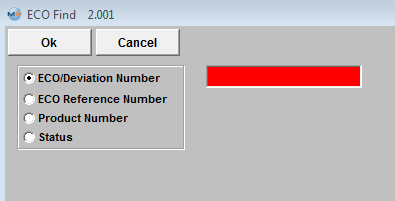
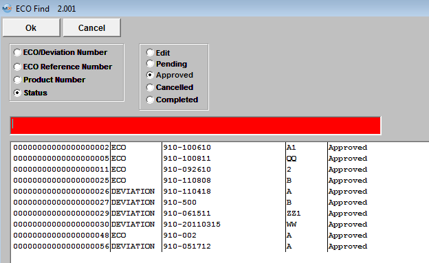
| 1.5.4.1. Find An Engineering Change Order(ECO), BOM Change Notice(BCN), or Deviation | ||||||||||||
|
The following screen will be displayed:
Information regarding the ECO, BCN, or deviation, will appear.
|


| 1.5.4.2. Edit an ECO, BCN or Deviation |
Find an existing ECO, BCN or Deviation. The information will populate the screen.
Depress the Edit record action button. Status will change to Edit.
Once the necessary changes have been completed depress the Save record action button to Save changes, or depress the Abandon changes action button to abandon changes. If the Save record action button is depressed, changes will be saved. The following screen will appear. NOTE: The Approvals will be removed and the ECO changes will need to be re-approved.
The changes will need to be Approved, before the ECO status will change back to Approved.
|
| 1.5.4.3. Adding A New ECO, BCN, or Deviation | ||||||||||||||||||||||||||||||||||||||||||||||||||||||||||||
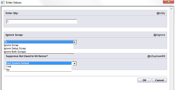
The following screen will be displayed:
Information pertaining to that part number will appear on the screen, as follows: 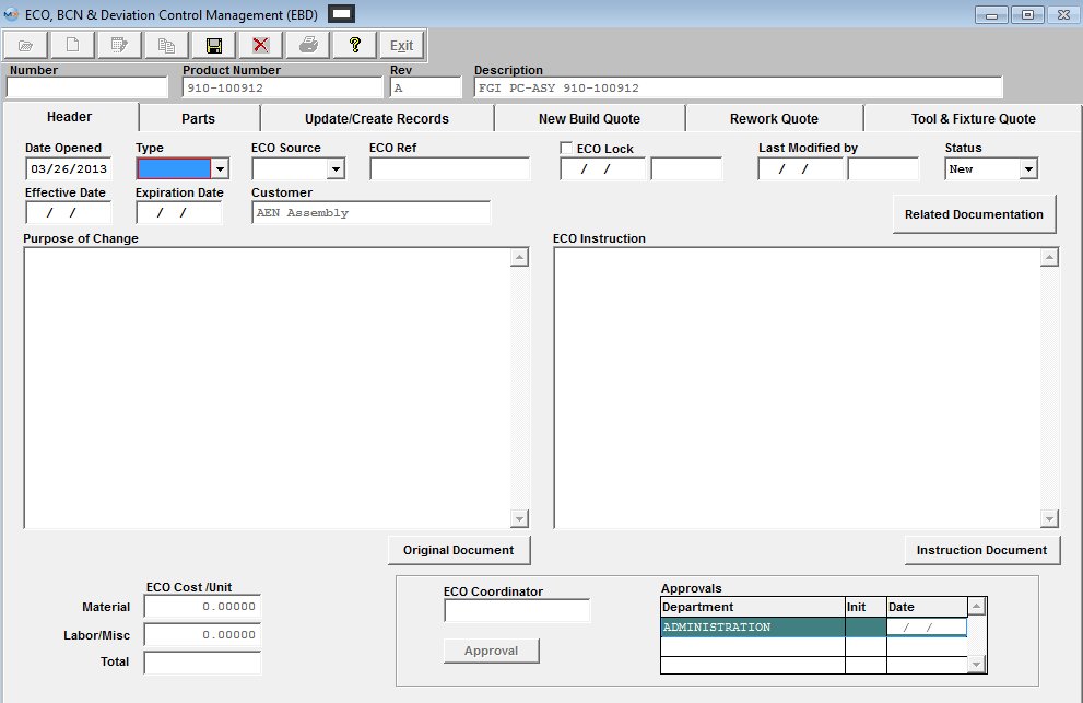
Enter in the ECO Reference, Effective Date. (Note: This date MUST be prior to the WO Due Date to be applied), Expiration Date if applicable (this field is only enabled when creating a Deviation), enter in the purpose of the change and Description of change, and name of the ECO Coordinator.
The screen will appear as follows: 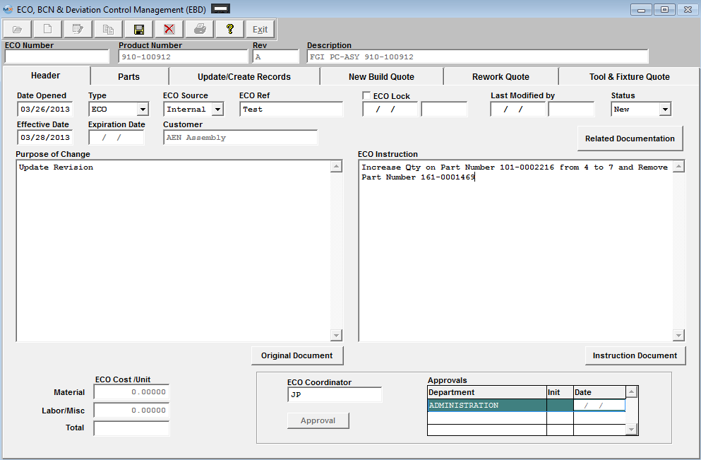 PARTS TAB Enter the Parts screen
To record an ADD to an ECO record Depress the Add Button.
The system will then default to the Status field. Depress the down arrow next to the Status field. The following choices will appear. Select Add from the Status listing. Enter in the new Line No that it will be listed as on the BOM.
Enter in the Part Number, and the Revision number, Type, Class, Description, and AVL information will update automatically. If the part added has a status of "Inactive" within the Inventory Control Management, it will be highlighted in purple as an indicator to the user that this item is inactive at this time. If the user chooses to leave the inactive part on the ECO, that part number record status will automatically be changed to Active upon the "Update Records" button being depressed, so user will not have inactive parts listed on the BOM. The user will receive a warning that an XLS file has been created for reivew. Enter in the new quantity to be used in the assembly, and Customer Part Number and Rev. if applicable. 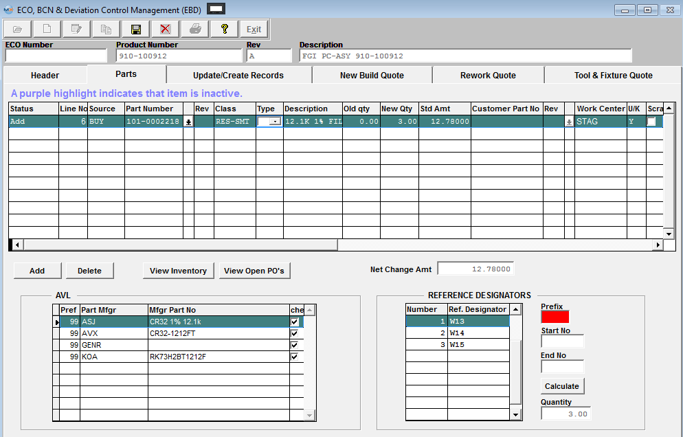
Scroll over to the right and select the Work Center by clicking within the Work Center field. The following selection screen will appear. The system will default into the U/K field, for the component to be included in the kit. You have the option to change this entry to one of the following Yes, No, or Free Stock.
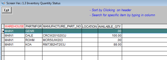
You will then be able to view the Inventory Locations for the highlight part number, by depressing the
To record a DELETE to an ECO Depress the Add Button.
The system will then default to the Status field. Depress the down arrow next to the Status field. The following choices will appear. Select Delete from the Status listing. Enter in the Bill of Material line Item, that you wish to have removed from the BOM. The screen will then update with the information pertaining to that item. Leave the New Quantity as zero. If you do NOT want the part scrapped, scroll to the right and remove the check mark from the Scrap Item field. (Note: This field is for internal reference only, it does NOT affect any other modules). To record a CHANGE to an ECO Depress the Add Button.
The system will then default to the Status field. Depress the down arrow next to the Status field. The following choices will appear. Select Change Qty from the Status listing. Enter in the Bill of Material line Item, that you wish to have changed on the BOM. The screen will then update with the information pertaining to that item. 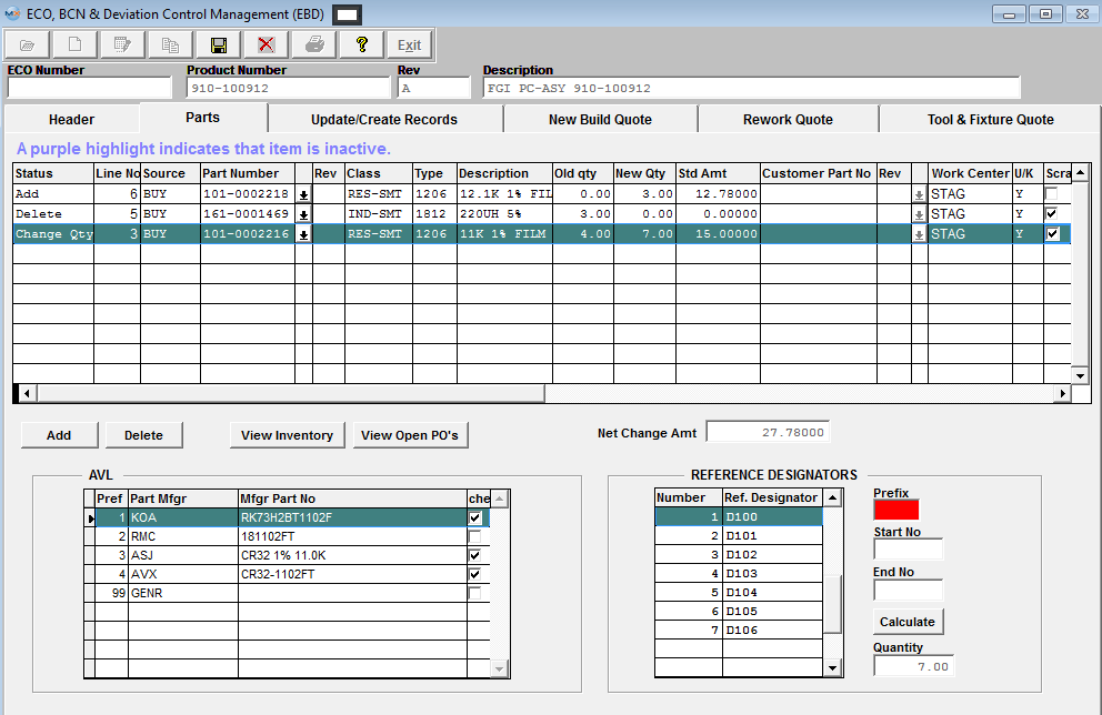 Enter in the new quantity. Update the Reference Designator information. In the U/K field, change to if you do not want the change to be used in the kit. If you do NOT want the item scrapped, remove the check mark from the Scrap Item box (Note: This field is for internal reference only, it does NOT affect any other modules).
To change the Work Center where the component is added, depress the down arrow next to the Work Center field. The following selection screen will be displayed: Make your selection. UPDATE/CREATE RECORDS TAB Enter the Update Records screens.(Note: that if the type was selected as Deviation within the Header screen, then the Update Records screen will be grayed out and unavailable for selection) Inventory Changes Section:
Check the applicable box and then Enter in a new product number, revision number, or new description, if desired.
NOTE: For the purpose of many users wanting to create several ECOs for the same product number without really updating the records (meaning creating a new part in inventory) Manex will allow you to save and approve the ECO even if they have not selected to create a new Part or Rev within the system. Upon depressing the Update Records button the system will check to see if New Product No or New Rev has been marked, if left blank then the system will just update the status of the ECO to Complete without creating a new product number in the system.
NOTE: When product is changed through ECO module the Material Type will be carried fwd to the next/new Product/Rev that is being generated at the part level, but will not carry fwd the material type at the AVL level. The system will default in "UNK" as the Material Type for the AVL Level.
To update the Material Cost, then check mark the box next to Matl Cost. The new Value field will update based on the changes made within Parts screen. To update the Labor Cost, then check mark the box next to Labor Cost. The New Value field will update based on the changes made within the New Build Quote screen. To require a serial number, then check mark the box next to Serial # Required. Then go to the box under the New Value column it will remain NO until checked then it will update to YES.
In the ECO process of modifying or adding Parts to the ECO, there is a field which contains the Customer Part number, if available. At the present time, this field is empty and non-editable for changing or deleting a part from the BOM. But if the user wishes to add a part, they may do so by entering in either the internal part number or the customer part number in the customer part number field, and the program will locate the corresponding internal part number and enter it. The search is based on the customer part number entered AND the customer associated with the BOM from which the ECO was originated. Because Manex allows users the ability to use the ECO module to create New Part Numbers via the ECO process, and even assign a new customer to the new part number, we must limit the customer information to that of the original customer, as we cannot determine at what point the reference should change customers, or even if it should. Furthermore, if the user does elect to create a new part number for a new customer, items unchecked on the AVL will transfer to the new bom (if checked on the update sheet). However, there may be a conflict between the AVL of the original customer and the AVL of the new customer, so the user is urged to verify the AVL content of a new bom for a new customer created with this module. COPY SECTIONS:
OPEN SALES ORDER LIST:
The Open Sales Order List will include all open Sales Orders including the ones that are flagged as "Admin Hold" and//or "Mfgr Hold", and any open RMAs against this product. Note: If there have been NO items shipped against the sales order selected then the system will just replace the existing product with the new product and/or revision within the Sales Order. If there have been shipments made against the item the old line item will have the Ord Qty updated to equal the total Shipped and the status changed to Closed. A new line item will have been created for the new Product/Rev for the remaining balance that was left on the original item. If you do NOT want the price changes to affect the sales order prices check the "Retain Sales Order Prices" box. If you would like to retain any extra charges against the line item check the "Retain Remaining Extra Pricing Items" box. Refresh SO button has been provided so the user can refresh the Sales Order list to check for any new SO created in the system since the ECO was first created. The completed screen will appear as follows:
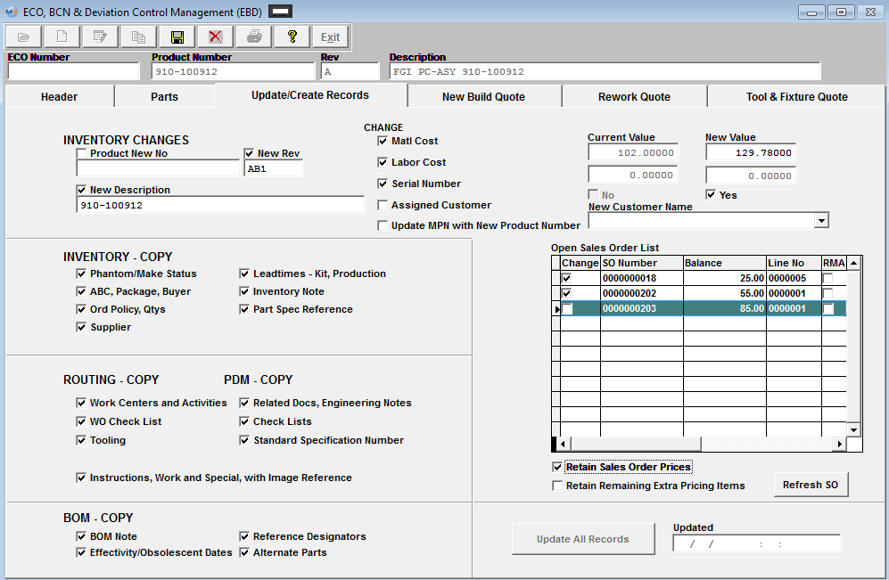 NEW BUILD QUOTE TAB Enter the New Build Quote screen. To add a new Labor Cost associated with the new revision, depress Add the button. Type in the Labor Cost Description. Type in the new revision cost per unit. Continue to Add as required. The completed screen will appears as follows: 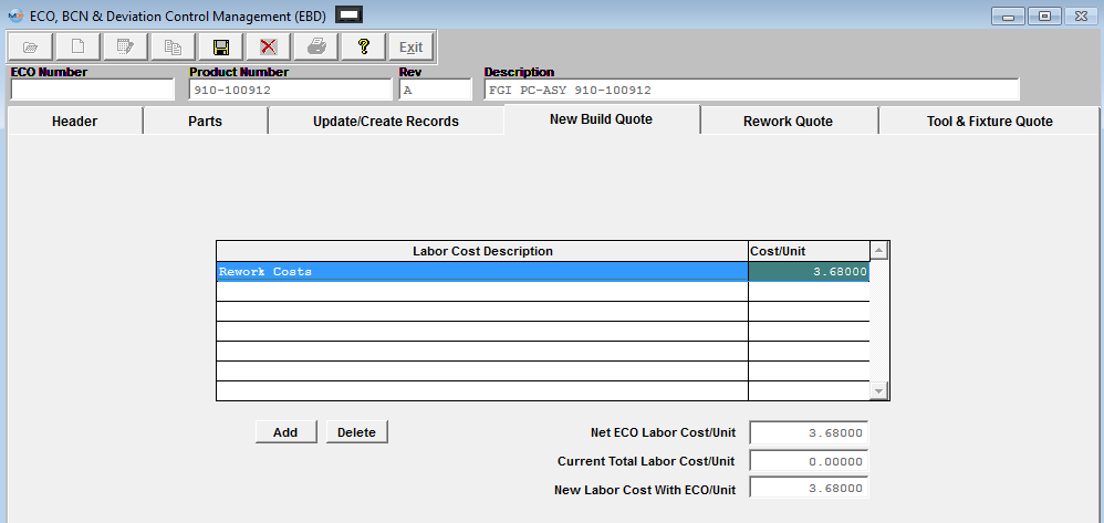 REWORK QUOTE TAB Enter the Rework Quote screen. In the Open WO List (As of ECO Open Date), check mark within the Change box column if you want the WO to be changed/reworked. The WO's checked will only be changed/reworked when creating an ECO. They will not be changed/reworked when creating a deviation. (This field is for reference only when creating a deviation).
You will receive the following message, as you check each box:
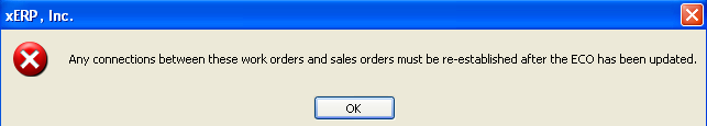 Depress the OK button to continue. If Work Order is shaded in WHITE - that means that this Work Order has no qty in FGI so the system will automatically update the Work Order to the New Revision. If a kit is in process for the Work Order selected user MUST depress the "Update Kit" button within the kitting module after the ECO is approved for any part changes to be reflected. NOTE: When the ECO takes place and the WO record is updated SFT losses the transfer history for the old revision and starts over with only xfer history for the new revision from that point on. See Article #3401 for further detail. If Work Order is shaded in BLUE - this means that this Work Order is partially completed and will be split into two Work Orders: The system will change the original Work Order (original product number and revision) build qty to match the qty completed and close this Work Order. The KIT for that work order will retain only enough material to build the completed quantities. The system will then create a new work order for new product number/revision for the balance quantity. All the extra material issued to the original work order will be de-kitted from original Work Order and issued to the new Work Order. If Work Order is shaded in PINK - These Work Orders are partially completed and some of the issued components are either serialized or lot code traceability activated. These specific components have to be de-kitted manually prior to proceeding. Or the original Work Order, has to be closed (balance reduced to completed quantities) and extra material de-kitted manually. Then, the new Work Order has to be created for the balance quantities. If needed, you have the option to refresh the Work Order listing to see if any new Work Orders have been created for this product since this ECO was originally opened, by depressing the "Refresh WO" button. To add costs solely associated with the rework of open Work Orders and/or Finished Goods Inventory, depress the Add button under the Rework Cost Description window. Type in the Rework Cost Description and the related cost per unit. The Inventory Locations (As of ECO Open Date), will default in and is for reference only. The Totals (As of ECO Open Date) will default in displaying the quantity in WIP and the quantity in FGI. The Units to Rework and the Cost to Rework will update automatically. If any new Work Order's were created they will be displayed in the "New Work Order" field for reference:
TOOL & FIXTURE QUOTE TAB To add new Tool/Fixture Information, depress the Add button below the section.
Add the Tool/Fixture information from the pull down.
Fill in the cost amount, Charge Amount, Effective Date, and Termination Date. Once the ECO record has been approved and updated within the system, this Tool/Fixture information will be carried forward into the PDM and Routing Setup modules. The completed screen will appears as follows: 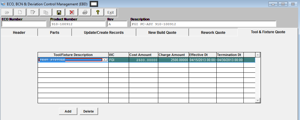 Depress the Header tab. Note that the ECO Cost/Unit columns have updated at the bottom left hand side of the screen: Upon Saving the user may be given a message if one or more of the parts do not have the same number of reference designators as the new quantity within the ECO, or BCN. This is giving the users the option to print out a report to list these item or not.  If Yes is selected the report, ECO Report Incorrect number of reference designators will go directly to the default printer and the next message will be displayed.
The user now has the option to cancel out of the save or continue. The user should go back to the reference designators section for the part listed in the report and change the number of designators to equal the quantity required.
The Approval button will be available. Depress the Approval button. You will be prompted for the appropriate department password. Continue this process until all of the departmental approvals have been entered, as displayed: Once all of the Approvals have been fulfilled then within the Update Records tab the “Update All Records" button will become available. Depress the Update All Records button. The records you selected will update. The ECO or BCN will now show with the following Updated time stamp.
Note: For a new revision, P/N, etc., go into the Inventory Master and if desired, update for the Warehouse location in the Quantity Information tab (the system will copy the warehouse information from original Product selected). Also, update for Mfgr Part Spec.
Overview: The difference between the ECO and the Deviation is: A Deviation is a method to document and approve a temporary change from the normal operation until an ECO is created to replace the Deviation, it is only a record that someone approved a change in some method for a work order(s). That is the reason the Deviation has an Expiration Date field in the main page and it will not update any active modules, part number change, rev change, description change or anything else. Whereas, ECO is a permanent change and change the part number, or rev or description, or standard cost, or anything thing else including updating any or all active files. The basic procedure of processing a Deviation follow basically the same rules as a Regular ECO except for the Update Records button is disabled.
Enter the ECO module. Depress the Add Record action button Select the desired product number. Then for the Type Select Deviation Once Deviation has been selected as the Type, continue on and enter in the remaining Deviation information as explained in the Adding ECO section above. Note: For a Deviation you MUST make sure you complete the expiration date so users know that it is for a limited period of time. If this field is left blank the deviation will NOT be displayed in the SFT module. 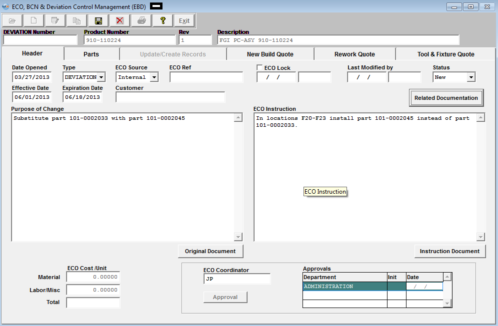 Note: The Update Create Records tab will remain grayed out and unavailable for any Deviation records entered within the system. Once the Deviation has been completed the normal list of Approvals need to be entered. The status of the Deviation record will update to Approved.
Changing the status of a Deviation from Approved to Completed. The Status of a Deviation will remain as Approved in the system until the users manually changes the status to Completed. Once the status of a deviation has been changed from Approved to Completed it will no longer appear in the SFT (Shop Floor Tracking) module.
Depress the Edit record action button. Click on the down arrow next to the Status field, the following selections will be available for Deviations.
Change the status to Completed. Depress the Save record action button to save the changes the changes, or depress the Abandon changes action button.
The Deviation will now show in the Status listing of Completed Records.
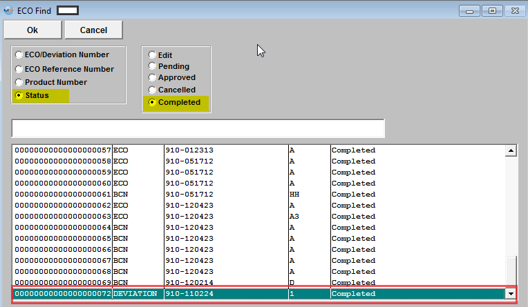 |
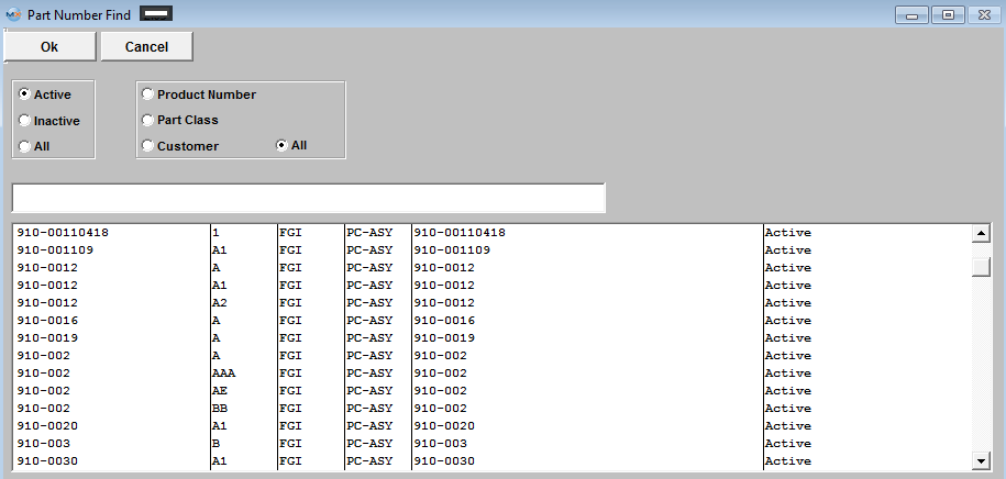


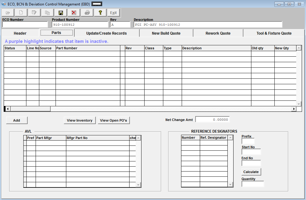

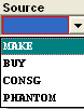
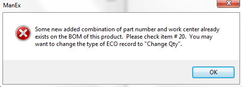
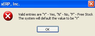
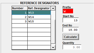
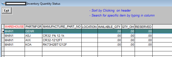
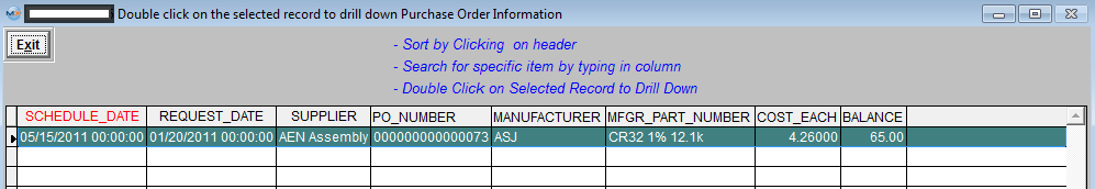
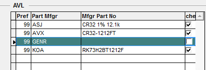
 cell
cell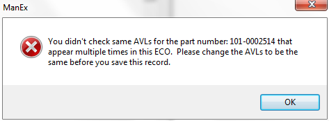
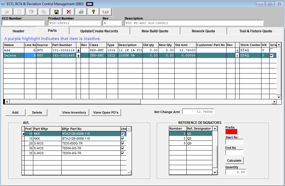
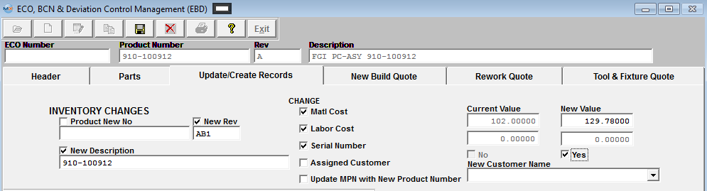
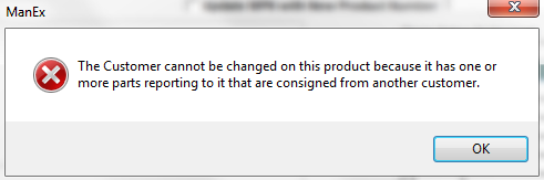
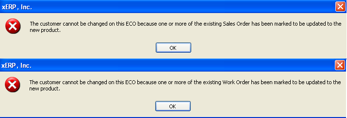
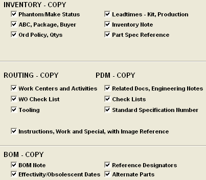
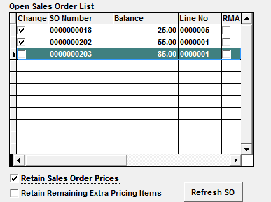
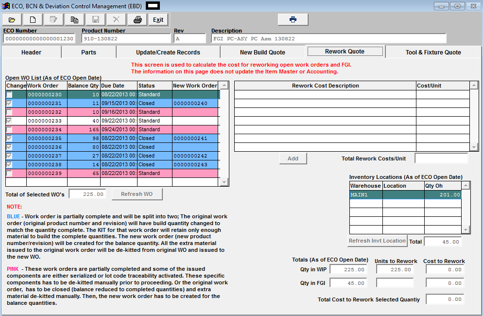
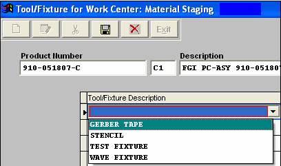
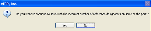
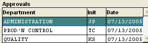
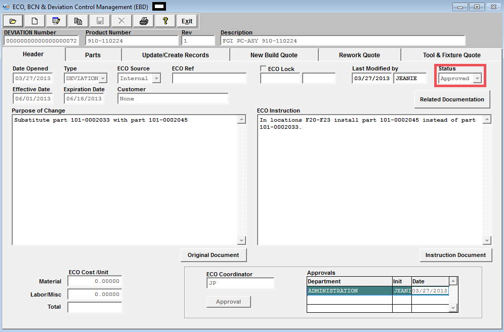
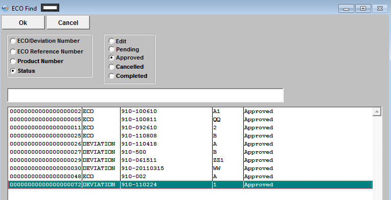
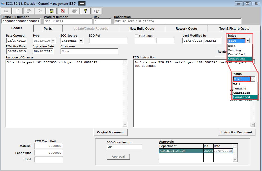
| 1.5.4.4. Copying An Engineering Change Order |
Enter the ECO module. Find an existing ECO record within the system. 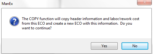 Select Yes, enter your password. Then the next message will be displayed:
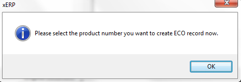 The following selection will appear:
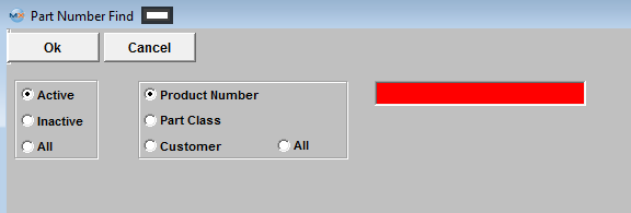 Once you have selected the desired product number the following will be displayed:
 The following information will be copied fwd from the original ECO to the new ECO record.
Header Information
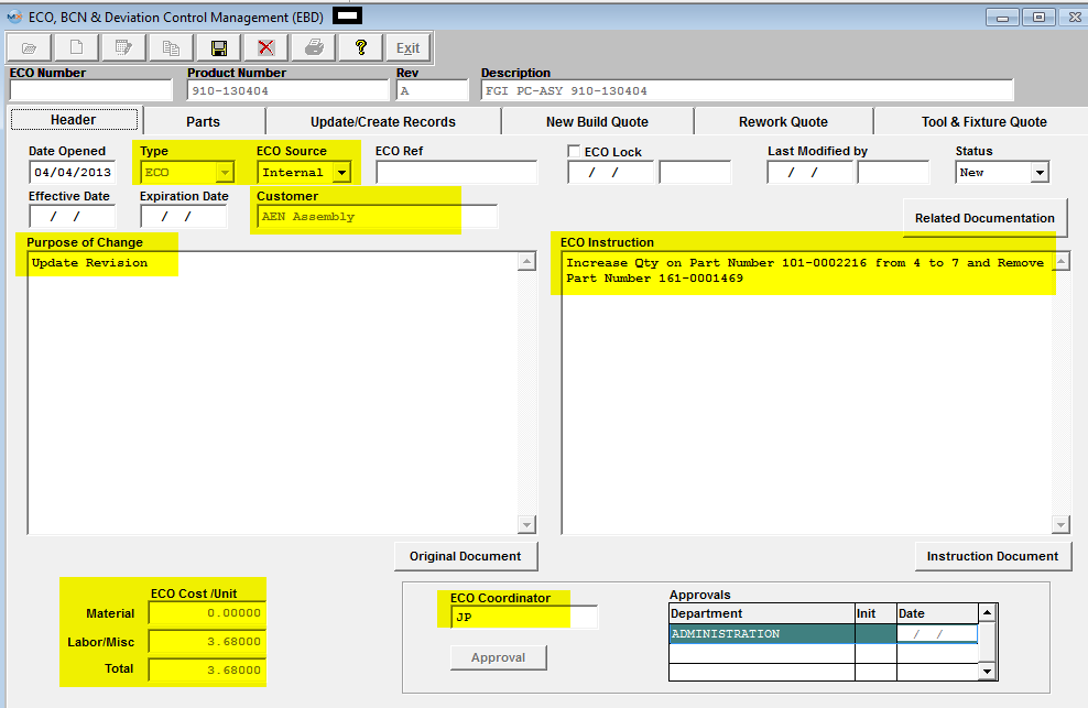 Update/Create Records Information
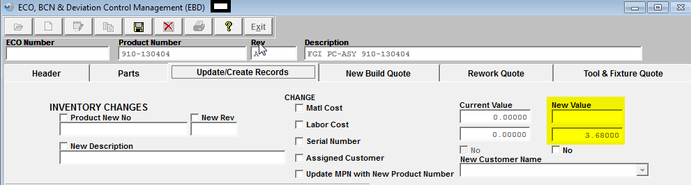 New Build Quote Information
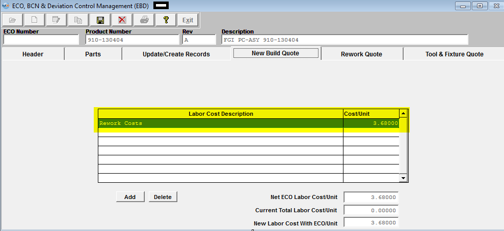 Rework Quote Information
|
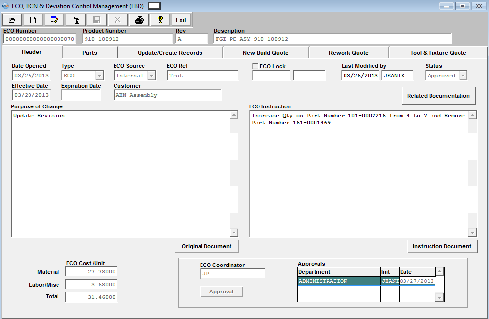
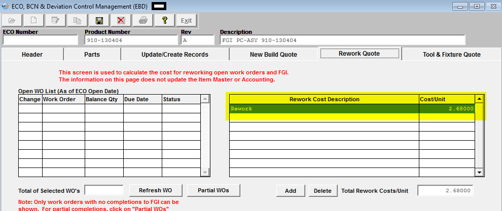
| 1.5.5. Reports - EBD | ||
|
To
obtain the ECO Reports within the Web, select the WEB Print button from the ManEx action
buttons at the top of the screen. For further detail on How the Reports work
within the Web refer to Article #5477. Note: In order to access the Reports within the Web the Company Root URL must be setup within the System Appearance module and user must be linked to web within the System Security Module.
Select the Report Type: ECO - A List of Reports will be displayed that are available on the Web for ECO
PRINT OUT OF ECO REPORT Select the Printout of ECO report and then depress the OK button and the following screen will be displayed: 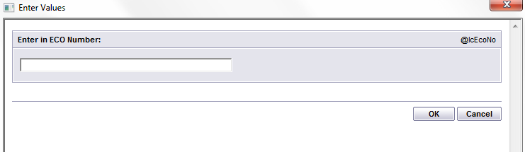 The ECO record that is open within the ECO module will default in – but the user does have the option to enter in a different ECO # record if desired. The ECO Printout Report will appear as follows:
ECO STATUS REPORT If you highlight the ECO Status Report and then depress the OK button and the following screen will be displayed:
Select the ECO Status and ECO Type by pressing on the down arrow next to the window. Highlight the desired status. Enter the Customer: (If All Customer are desired leave * as default) NOTE: You MUST enter a Customer or have the default (*) for this report to work. If the ECO record does NOT have a Customer selected, then it will NOT appear on this report. Enter Starting Date Range and Ending Date Range in "yyyy-mm-dd" format Enter Starting Part Range and Ending Part Range: (If all parts are desired leave * as default) Depress the OK button. The following ECO Status Report will appear as follows:
|
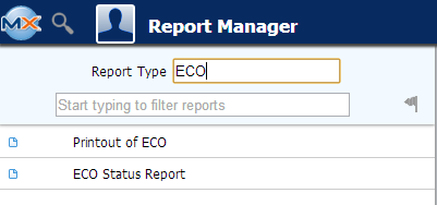
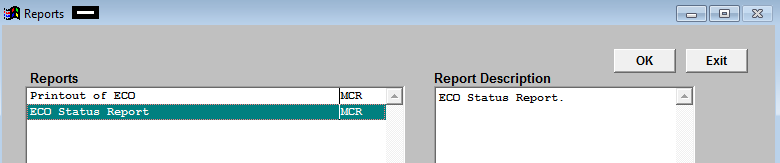
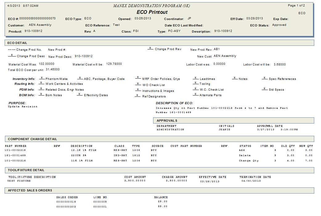
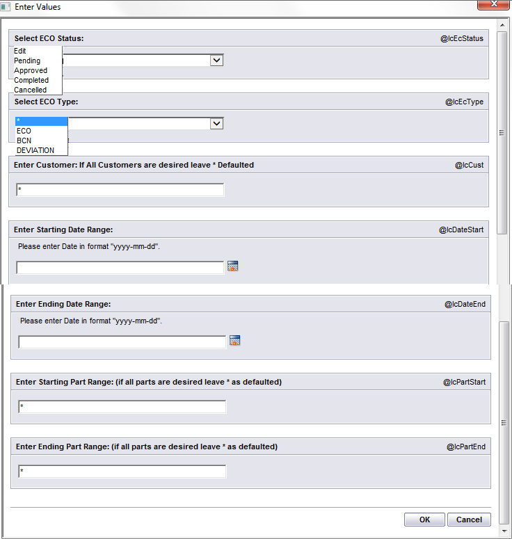
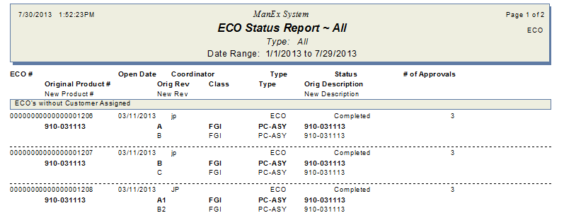
| 1.5.6. FAQs- EBD |
| Facts and Questions for the ECO, BCN & Deviation Control Mgmt (EBD) Module |
| 1.6. Work Order Traveler Setup |
| 1.6.1. Prerequisties for WO Traveler Setup | ||||||||
After activation, "Product Routing" access for each user must be setup in the ManEx System Security module. Users with “Supervisor Rights” will automatically have access.
|
| 1.6.2. Introduction for WO Traveler Setup |
The Work Order Traveler Setup module is used to define the details of the Production Work Order Traveler Setup for a product. Certain work centers are “hard-coded” into the ManEx program. These are Material Staging, Finished Goods, RWRK, RWRKQC and Scrap. These work centers may not be modified by the user, or omitted from a Work Order Traveler Setup, because they are associated with special codes that are essential to our system.
RWRK and RWRKQC are used to move material directly to Rework Work center and rework Quality Control Work center. Would be used for RMA's ect... |
| 1.6.3. Fields and Definitions for WO Traveler Setup |
| 1.6.3.1. Header | ||||||||||||||||||
Work Center and Activities Routing Setup Header Field Definitions
|
| 1.6.3.2. Work Center Tab | ||||||||||||||||||||||||||
Fields and Definitions
|

| 1.6.3.3. Activities Tab | ||||||||
|
The activities tab is used to add specific activities that take place within a Work Center. For the Work Center which is highlighted within the Current Work Center field, the Activities Tab will change to RED text if activities have been assigned to that work center. Within the window, the 1st column is the abbreviation used for the activity and the 2nd column is the full activity for the Work Center listed. The list of activities are set up in System setup – Production Work Centers & Activities. 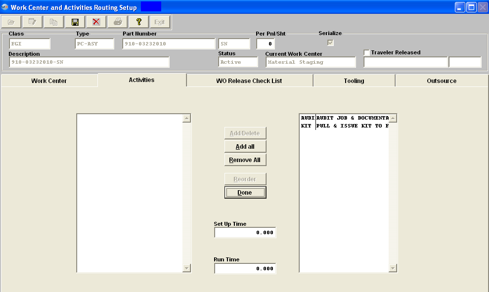 Fields & Definitions
This button is used to add or delete activities for the Work Center listed. This button is used to reorder the list. Setup Time For the activity highlighted, this field is for the set up times. If user enters setup time at activity level the system will accumulate the times for all the activities (for that specific work center) and assign it to the WC level and overwrite whatever number if any entered there. |
| 1.6.3.4. WO Release Check List Tab | ||||||||
The Work Order Release Check List tab is for the user to select check list items for the Work Center listed in the Current Work Center field. The Work Order Release Check List is set up in the Shop Floor Tracking Default set up screen. In this module, the Check List items are selected, as detailed. Then when the user reaches the Work Order Shop Floor Tracking module, the items added in this module will be available.
Fields & Definitions
This button allows the user to add or delete the check list items to or from the Work Center being displayed above. |
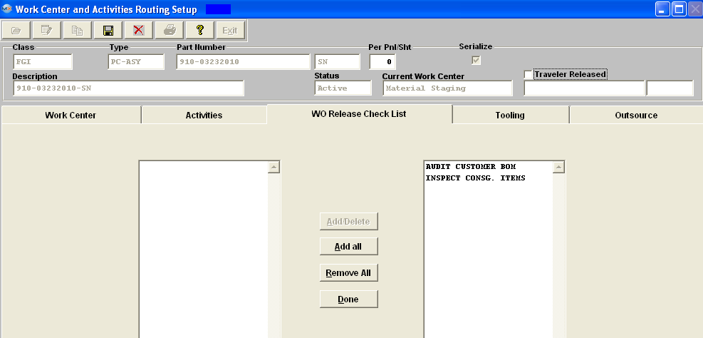
| 1.6.3.5. Tooling Tab | ||||||||||||||||
|
The Tooling tab is used to describe the tooling requirements for the Work Center. It also provides for a location notation and an Expire Date. An example of a Check List item as discussed above might be to perform the Work Center tooling, as detailed in this tab.
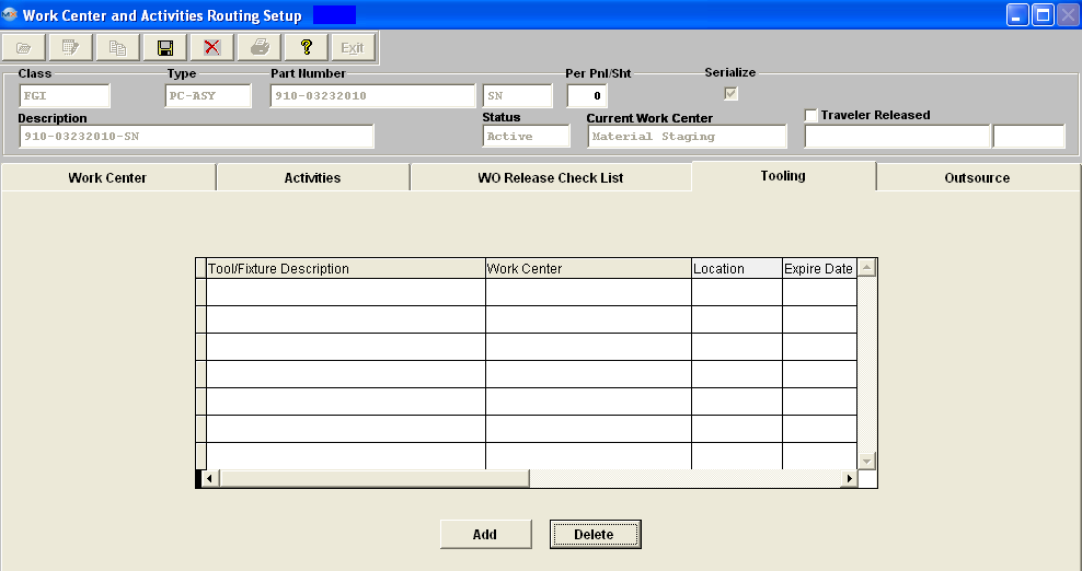 Fields & Definitions
|
| 1.6.3.6. Outsource Tab | ||||||
The Outsource tab shows the services to be performed outside of the user’s shop. These services are indicated with an “O” in the work center tab. Within the window, the 1st column is the abbreviation used for the activity and the 2nd column is the full activity for the Work Center listed. The list of activities are set up in System setup – Production Work Centers & Activities Setup.
|
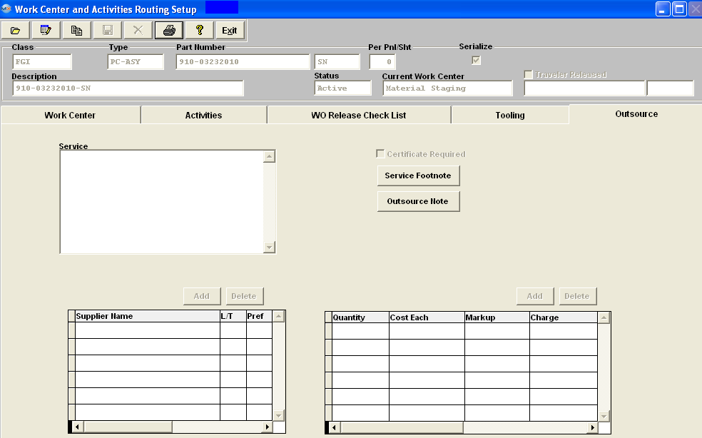
| 1.6.4. How To ..... for WO Traveler Setup |
| 1.6.4.1. Find a Work Order Traveler | ||||
Enter the SQLMANEX.EXE (within the ManEx root directory) The following screen will be displayed, select Quality Engineering/Work Order Traveler Setup The following screen will be displayed:
In this screen, a Work Order Traveler setup is either Created or Edited.
Depress the Find record icon, the following dialog box will be displayed: If user elects to find by the Product Number or by Part Class they must enter in the Product Number or Part Class in Red box. If you do not know the exact number, Customer, etc you may enter in a partial number, letter, etc, then once you depress the enter key the system will pull up the matching record onto the screen or a list of all Part Numbers that contain the partial number, letter, etc. entered, to select from.
If user elects to find by selecting the "All" radio button. The user selects the desired product by either entering it into the red box, or scrolling down the list and double-clicking on the desired product.
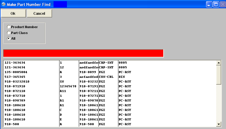 The following screen will be displayed with the data for the selected product.
. |
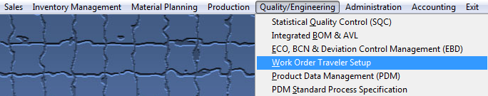
| 1.6.4.2. Setup/Edit a Work Order Traveler Routing | ||
Setup a Work Order/Traveler Routing
Find the desired Product number record. 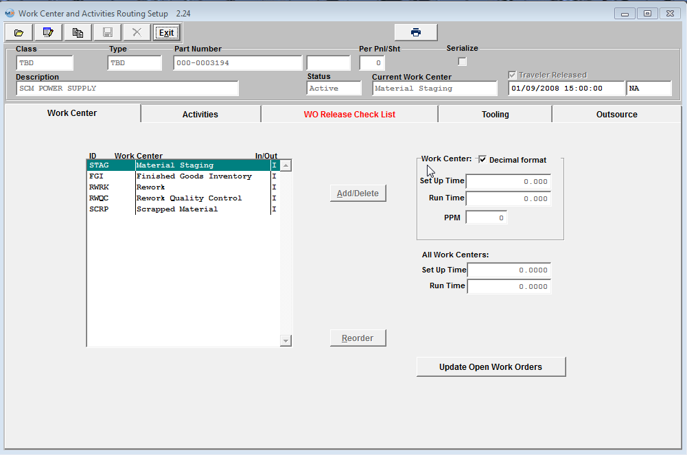 Depress the Edit button from the main tool bar: Note: Users MUST have special rights within the Security module to check the "Traveler Released" box. Users with “supervisor’s rights” will automatically have access. This box must be check when usiing the Unreleased Work Order List and the Work Center Checklist . User may Add/Delete Work Centers, by depressing the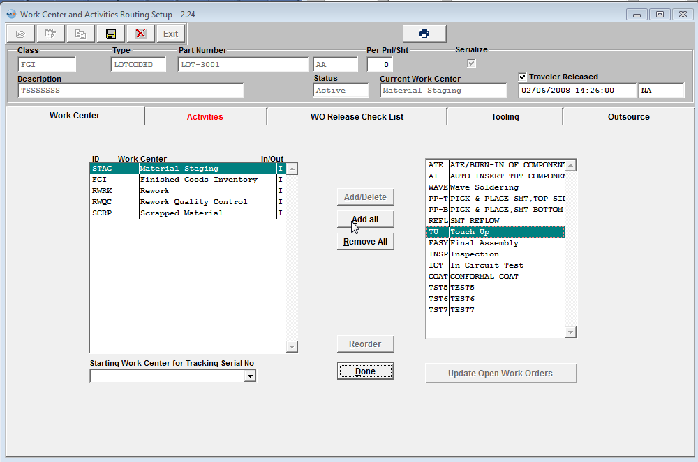 Work Centers may be moved to either side by double clicking on the side from which to move.
If the user wishes to add all work centers to the Work Order Traveler Setup, then remove a few unwanted ones, pressing the “Add All” button will transfer all work centers to the Work Order Traveler Setup. Likewise, pressing the “Remove All” button will remove all but the fixed work centers from the Work Order Traveler Setup. Work Order Traveler Setups may be added more than once, to accommodate multiple visits to the same work area during production (e.g. test).
Depress the Done button when the movement is completed. The "Reorder" button allows the user to reorder the Work Order Traveler Setup in any order desired. Pressing this button will bring up ordering buttons on the left side of each work center in the Product Work Order Traveler Setup. The user may then click on any of these buttons and drag a work center to the desired order. Depress the Done button when the reordering is completed.
 "Starting Work Center for Tracking Serial No" Choose from the pull down which Work Center you would like to begin tracking the Serial numbers. The system does NOT allow selection of "FGI" or "SCRP" as a starting WC for Serialization, because this will cause the system to become stuck between SFT and Serial number assignment. NOTE: If the starting work center is removed, when user clicks “Update WO” button, all the WC qty and SN (if any) except for FGI, RWRK, RWQC, and SCRP work centers will be moved back to STAG work center because the system will treat the STAG as the starting tracking SN work center. 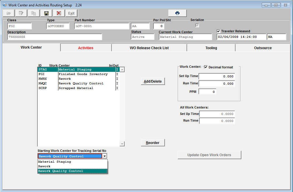 User may enter/edit the WC Setup/Run time or the PPM. The user should place the cursor on the work center to be edited, then on the times to be edited. The user may modify one or more Work Centers. The area labeled "All Work Centers", will show the total times of all work centers and/or activities. This will automatically update. Note: There are two different ways to track SETUP and RUN times for Job Costing and Product Data Management in ManEx.
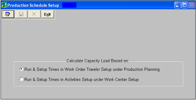 1. By entering Run and Setup Times in the Work Order Traveler Setup under Production Planning. 2. By entering the Run and Setup Times in Activities Setup under the Work Center Setup. Using the first choice is preferred when there is a great variability in the products produced and the setup and run rates in each work center. The second choice is preferred when the product flow is uniform, the machine rates are well established and the setup times very uniform regardless of product. The choice is made in the Production Schedule Setup module. Use of Run and Setup Times is optional unless Job Costing module is in use. Then depress the Save button from the main tool bar to save the changes and the Update Open Work order button becomes enabled.
After modification, the user must either Save or Cancel the modifications. |

| 1.6.4.3. Copying a Work Order Traveler Setup | ||||||
Find the desired Product Number, that you wish to have updated.
|
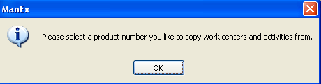
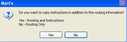
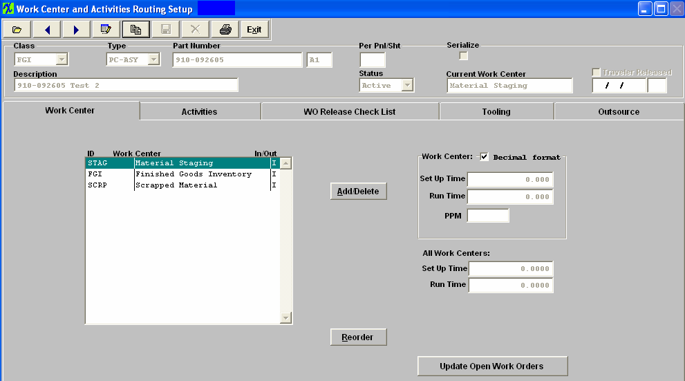
| 1.6.4.4. Setup/Edit Work Center Activities |
Note: if a Work Center has activities associated with it, the “ACTIVITIES” tab will be showing in RED font.
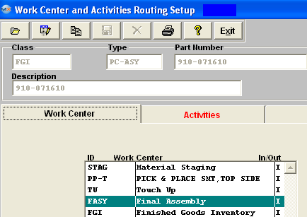 Add/Removing Activities In the Activities screen, the user may add or modify activities and Setup/Run time associated to that activity.
The activities must have been set up in the Production Work Centers & Activities module and be attached to the Work Center.
Activities may be moved to either side by double clicking on the side from which to move. The
If the user wishes to add all activities, then remove a few unwanted ones, pressing the “Add All” button will transfer all activities to the Work Order Traveler Setup. Likewise, pressing the “Remove All” button will remove all activities from the Work Order Traveler Setup.
Depress the Done button when the movement is completed. The "Reorder" button allows the user to reorder the activities in any order desired. Pressing this button will bring up ordering buttons on the left side of each activity in the Product Work Order Traveler Setup. The user may then click on any of these buttons and drag an activity to the desired order.  Depress the Done button.
When in Edit mode, user may add/edit Setup Time and/or Run Time to an activitiy associated with a work center.
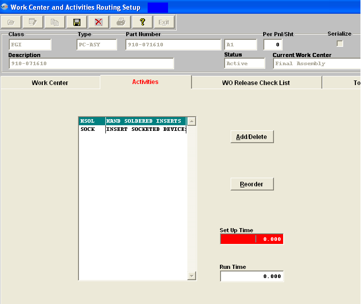 Note: If user enters setup/run times at activity level the system will accumulate the times for all the activities (for that specific work center) and assign it to the WC level and overwrite whatever number if any entered there. If the user tries to change the WC setup/run times they will receive a warning that there are setup/run times at the activity level and these must be removed before they will be allowed to change the WC setup/run times. If the user decreases the activity setup/run times to 0 or remove the activity, then the user can add or edit the WC setup/run time. After modification, the user must either Save or Cancel the modifications. |
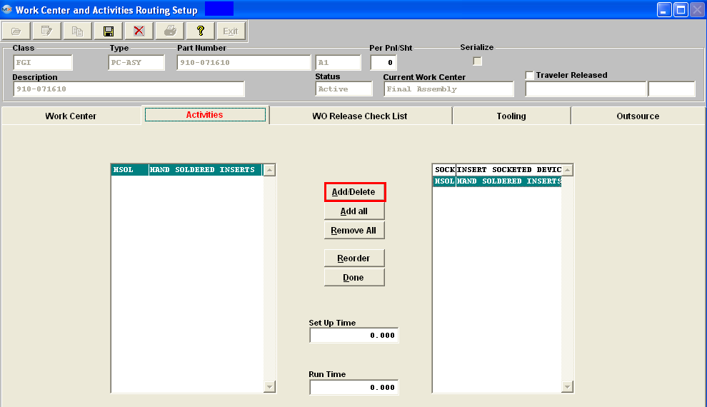

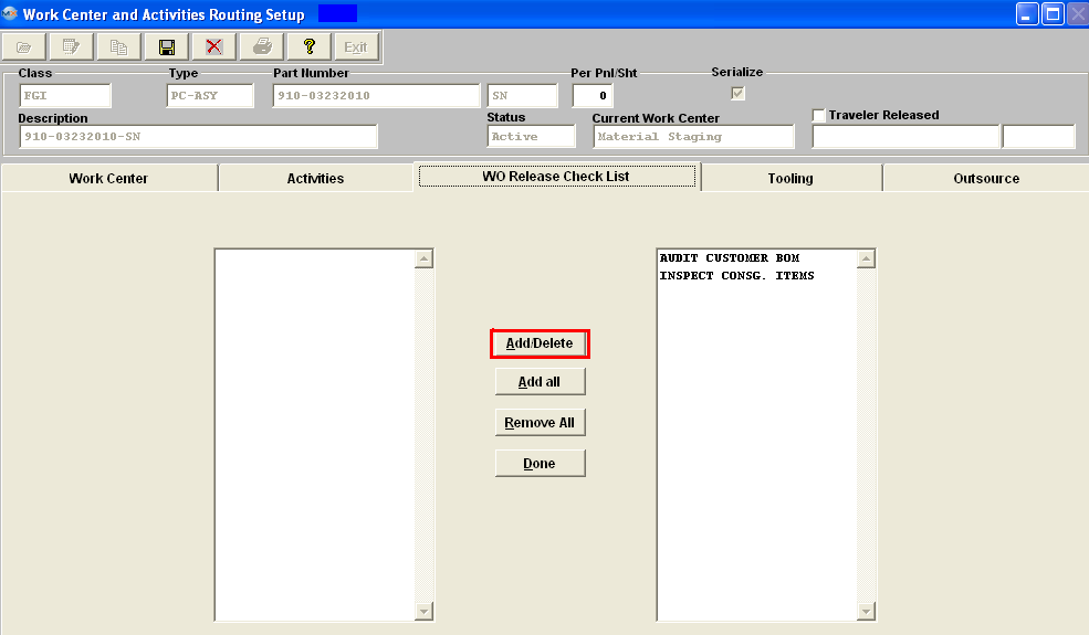
| 1.6.4.6. Add/Edit Tooling Information | ||||||
Adding/Editing Tooling Information
The Tooling tab is used to describe the tooling requirements for the Work Center. It also provides for a location notation and an Expire Date. An example of a Check List item might be to perform the Work Center tooling, as detailed in this tab. Find the desired Product number record.
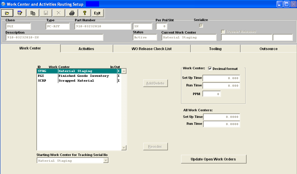 Depress the Edit button from the main tool bar, or enter the Tooling screen then depress the Edit button from the main tool bar: 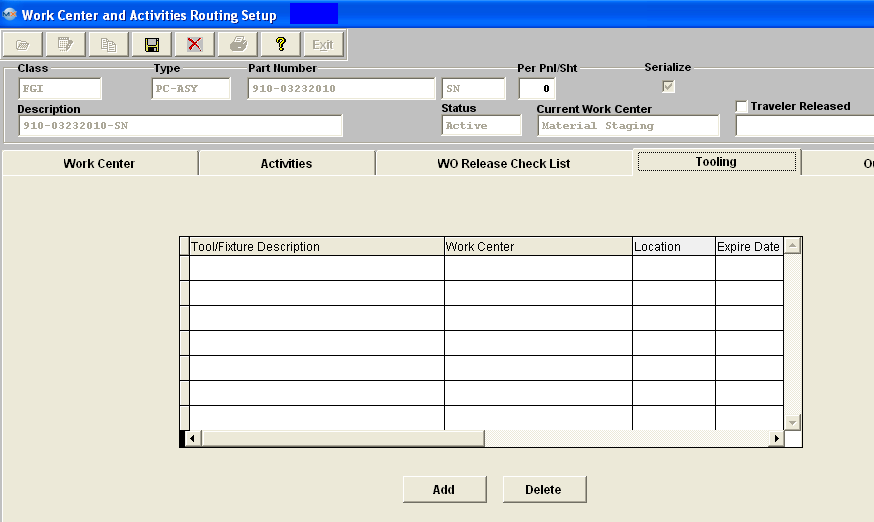 To add a Tool/Fixture depress the "ADD" button.
Select the Tool/Fixture Description from the pull down selections (setup within the Tools Setup module). Enter the Location, and the Expire date. The completed screen will appear as follows:
To delete a line item from the Tooling Tab. Highlight the line item. Depress the Delete button, the following message will appear. Select Yes to continue the deletion, select No to abandon the deletion. |
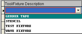
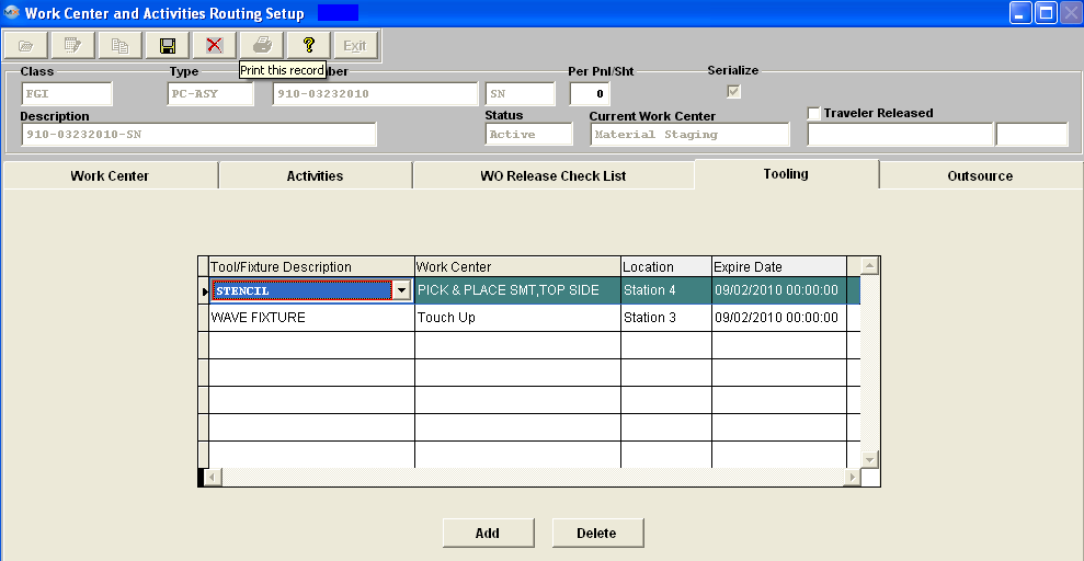
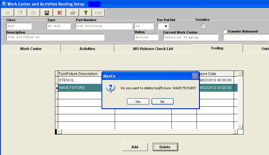
| 1.6.4.7. Add Outsource Information |
|
The Outsource tab shows the services to be performed outside of the user’s shop. These services are indicated with an “O” in the work center tab.
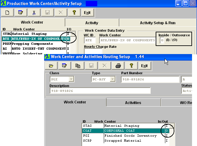 Highlight the Outsource Service, then go to the Outsource Tab and the following screen will appear: 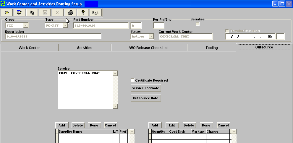 Highlight the Outsource Service. Depress the Add button for the Supplier. Select the Supplier from the pull down. Then continue across the columns and enter the quantity, cost each and markup. The Charge column will automatically update. When data entry is complete, depress the Done button.  In a future release, outsourcing will be available to create POs, receivers, etc. If the "Certificate Required" box is checked, this indicates that the supplier of the outsourced service is required to provide a certificate of completion. Depress the "Service Footnote" to attach a footnote regarding the services for this product. Depress the "Outsource Note" to attach a note regarding the outsourcing for this product. If you want to add a Service Footnote or an Outsource note, depress the applicable button. Depress the Edit button. Type in the note. Depress the Save button. Depress the Exit button. Depress the Save button at the top of the screen to save changes, depress the Abandon changes button to abandon changes. |
| 1.6.5. FAQs - WO Traveler Setup |
| Facts and Questions for the WO Traveler Setup Module |
| 1.7. Product Data Management (PDM) (OPTIONAL Module) |
| 1.7.1. Prerequisites for PDM | ||||||||||
Prerequisites Required For PRODUCT DATA MANAGEMENT:
ManEx’s standard module configuration allows most users to accomplish their daily tasks. For those users wanting to get more from ManEx by leveraging the total solutions, this is one of the optional modules available for purchase. To place an order or to learn more about this specific module or any of the other optional modules please contact us at http://manex.com\contactus.aspx
After activation, "Product Data Management" (PDM) access for each user must be setup in the ManEx System Security module. Users with “Supervisor Rights” will automatically have access.
Optional Prerequisites for Entering a New PRODUCT DATA MANAGEMENT:
If images are to be included in Work Instruction and Set Up Instruction view screens. |
| 1.7.2. Introduction for PDM |
The Product Data Management (PDM) Module is the place where Engineering may establish work instructions, setup instructions and/or checklists. References to related documentation, Engineering notes, and production feedback on the product is also available. With the PDM module, the user may create both text instruction and graphical images. Once a product has been established, similar products with some or all of the same instructions can have instructions copied from the original product, then modified to suit requirements. The work instructions are available to users in the shop floor module, and users may elect to print the work instructions in the Work Order Traveler Setup traveler module. Information entered in this module can be accessed via the Shop Floor Mgmt module. Work Instructions, Special Instructions, Documentation, Work Center Check List and Notes are available. |
| 1.7.3. Fields & Definitions for PDM |
| 1.7.3.1. Header Information | ||||||||

|
| 1.7.3.2. Routing Tab | ||||||||||||||||||||||||||||
|


| 1.7.3.3. Check List Title Screen | ||||||||||||||||
This screen allows the user to establish check lists for each PRODUCT. Note that this is a different check list than the one for Work Order which is set up in Shop Floor Tracking Defaults . Items may be added to the check list in the edit mode.
This information will be carried forward into the Shop Floor Tracking module for the highlight Work Center. |
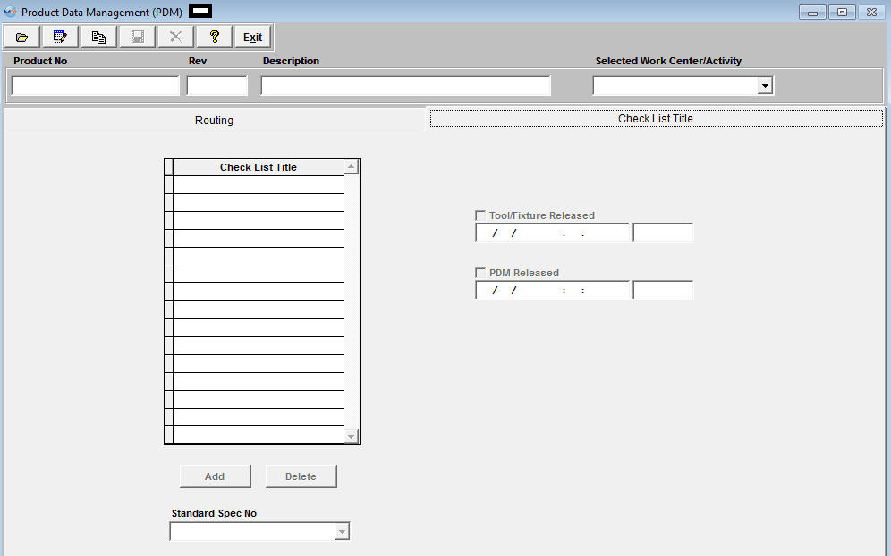
| 1.7.4. How To ..... for PDM |
| 1.7.4.1. Finding A Product Data Management Record | ||||||||
The following screen will be displayed: 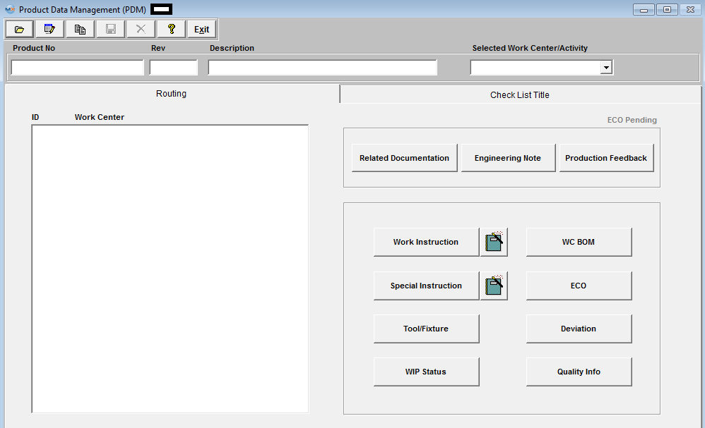
If the user selected to find by All. All the Product Numbers within the Inventory records will be displayed to select from: 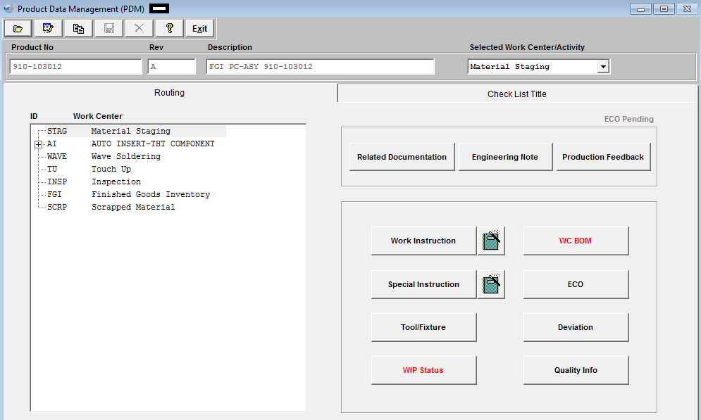 The plus (+) mark preceding work centers indicate that additional activities are included in the work center, and may be viewed by clicking on the plus sign.
|
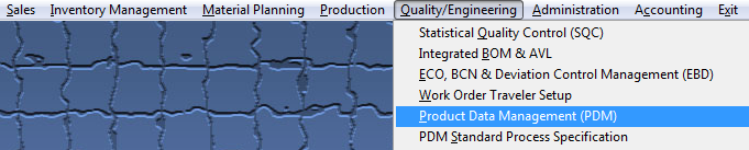
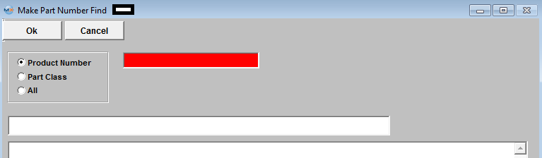
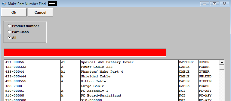
| 1.7.4.2. Add Information to the PDM Module | |||||||||||||||||||||
Find a PDM Record.
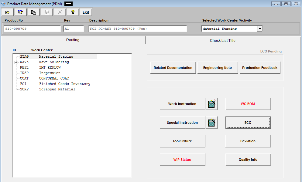 To attach Related Documentation See Article #2396 . Once the information is loaded, the user may re-visit the Documentation in the PDM module and may also access the information from the Shop Floor Tracking Module.
See Article #3272 on how ManEx can help to simplify the process of identifying, tracking, and eliminating attrition and scrap.
WIP Status - displays the WIP Status of all the open work orders for this product and displays where the quantities are in the shop floor.
 WC BOM - The part numbers that are assigned to that specific
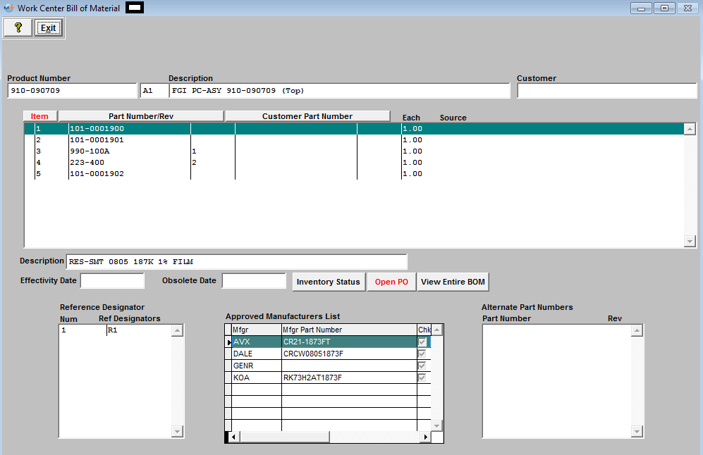

 ECO - All of this information is carried forward from the ECO Control Management module. If the highlighted part number within the Part Change Information section was added as a Consigned item, then the associated Customer Part Number information will populate the field. EXIT will bring you back to the Product Data Management module.
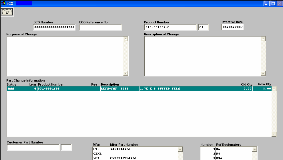 Deviation - All of this information is carried forward from the ECO Control Management module. If the highlighted part number within the Part Change Information section was added as a Consigned item, then the associated Customer Part Number information will populate the field.
Quality Info - This screen will display Quality information for the Product that is displayed for the selected work center.
Once you depress the OK button the following screen will be displayed. You can then change the selections to view All Work Centers if need.
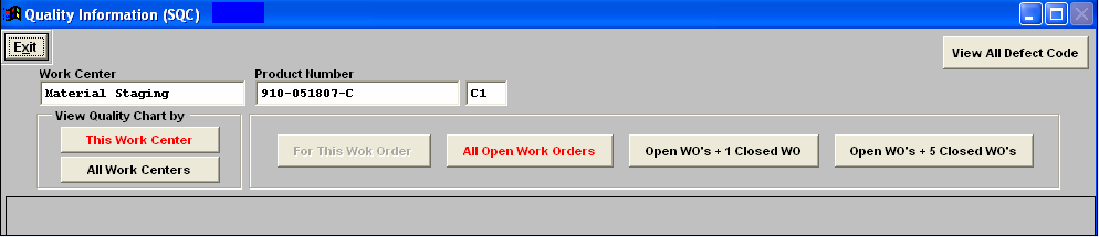 If there has been Inspection information entered for the highlighted work center then the following screen will be displayed. The Quality information displayed on screen will appropriately update as the user selects the desired button selections. Exit will bring you back to the Product Data Management Module.
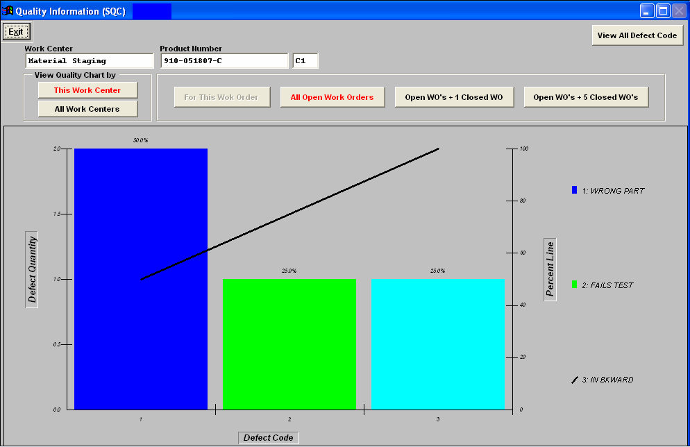
|
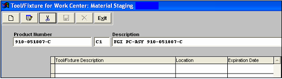
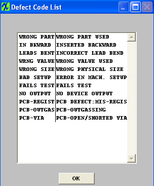
| 1.7.4.2.1. Load Document | ||||
The following screen will appear:

The file will appear in the screen as displayed:
 Depress the Save action button to save the changes or depress the Abandon changes action button to abandon changes. Exit will bring the user back to the Product Data Management module.
All files and images planned to be used within the Product Data Management module should be stored in a permanent directory on the server, which users will have read access to. The user will define the directory and file for each product in this module, but the information will be available elsewhere throughout the manufacturing module. |
| 1.7.4.3. Setup a Checklist | ||||
Find a PDM Record.
Depress the Check List Title tab. The following screen will be displayed:
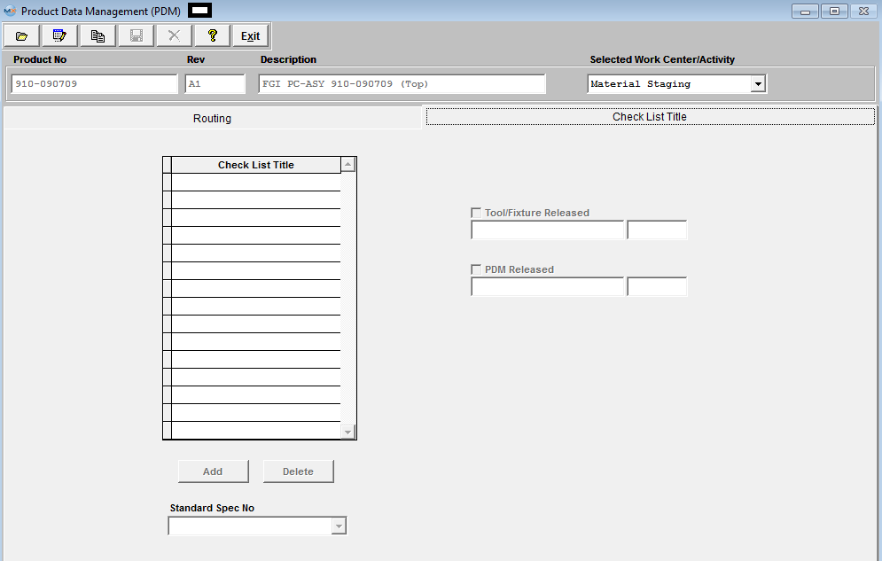 This screen allows the user to establish check lists for a specific Work Center for a specific PRODUCT. This checklist is for users to check if they do all the necessary task, but it does NOT enforce the user to check all items before the user can transfer to next WC. Note: this is a different check list than the one setup for Work Orders which is set up in Shop Floor Tracking Defaults .
.
To Create the Check List, depress the "ADD" button and enter all the necessary information under the Check List Title per product number/work center directly. Depress the "ADD" button to enter a new specification under the Check List Title until the Check List complete for that specific Work Center/Activity.
 Pressing the DELETE button deletes the item that the cursor is on when the delete button is pushed.
While screen is in Edit mode, user may also check the Tool/Fixture Released and/or PDM Released boxes. Note: Users MUST have special rights within the Security module to check these boxes. Users with “supervisor’s rights” will automatically have access. These boxes must be check when usiing the Unreleased Work Order List and the Work Center Checklist .
 Depress the Save button to save changes or depress the Abandon changes button to abandon changes. The completed screen should appear as follows:
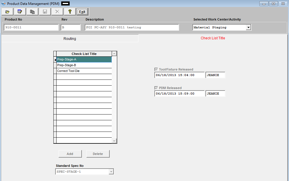 This information will be carried forward into the Shop Floor Tracking module for the highlight
 |
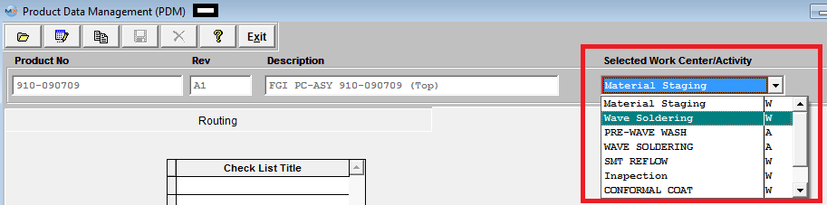
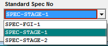
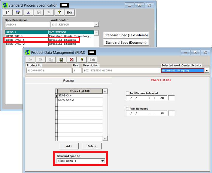
| 1.7.4.4. Copy Information from another Product | ||||||||||
Find a PDM Record.
The following screen will appear:
|
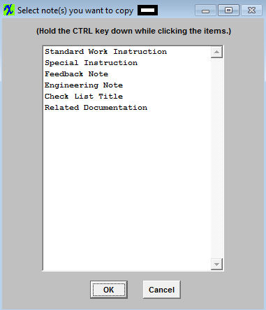
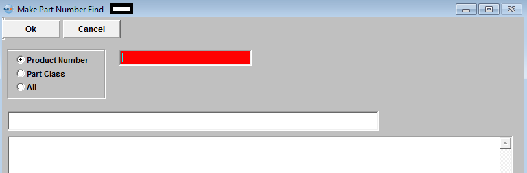
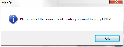
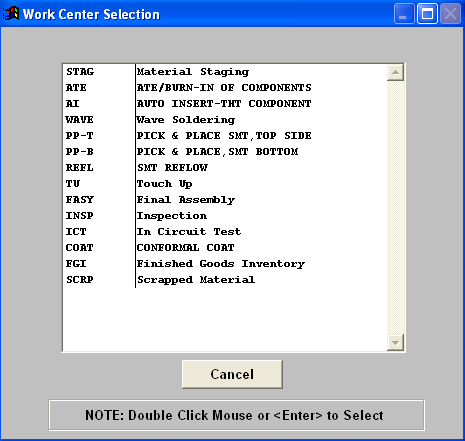
| 1.7.5. FAQ's - PDM |
| Facts and Questions for the Product Data Management (PDM) Module |
| 1.8. PDM Standard Process Specification |
| 1.8.1. Prerequisites for PDM Standard Process Specifications | ||
|
ManEx’s standard module configuration allows most users to accomplish their daily tasks. For those users wanting to get more from ManEx by leveraging the total solutions, this is one of the optional modules available for purchase. To place an order or to learn more about this specific module or any of the other optional modules please contact us at http://manex.com\contactus.aspx After activation, "Standard Process Specifications" access for each user must be setup in the ManEx System Security module. Users with “Supervisor Rights” will automatically have access.
|
| 1.8.2. Introduction for PDM Standard Process Specification |
The PDM Standard Process Specification Module is the place where Engineering may establish process specifications. Text and pictures may be included in detailing the specifications. Standard specifications relating to the Work Center can be accessed in the Shop Floor Tracking Mgmt module. |
| 1.8.3. Fields & Definitions for PDM Standard Process Specifications | ||||||||
|
| 1.8.4. How To ...... for PDM Standard Process Specifications |
| 1.8.4.1. Add a PDM Standard Procress Specification | ||||||||
The following screen will be displayed:
Depress the Add Record button. You’ll be prompted for your password. Enter in the Specification Description, then select the Work Center from the pull down:
To load images or documents, depress the
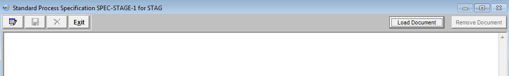
The file will appear:  Depress the Save button to save the changes or depress the Abandon changes to abandon the changes. Depress the Exit button will bring you back to the Standard Process Specification. module.
All files and images planned to be used within the ManEx system should be stored in a permanent directory on the server, which users will have read access to. The user will define the directory
and file for each product in this module, but the information will be available elsewhere throughout the manufacturing module. The complete screen will look like this.
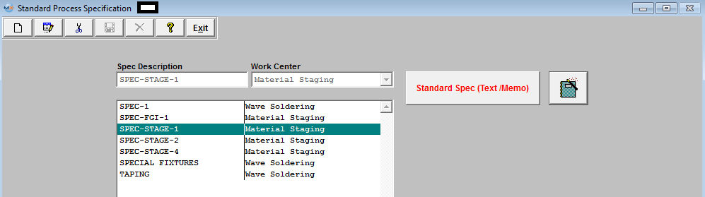 Note: The Standard Spec button is now being displayed in Red.
User may add more standard process specifications, edit or delete existing specifications or exit.
Once the Standard Spec is assigned to a Work Center in the Check List Title.
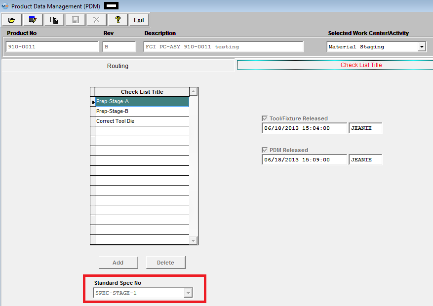 This information will be carried forward into the Shop Floor Tracking module. NOTE If there are existing Work Orders to update user MUST go to the Work Order Traveler screen and depress the"Update Open Work Orders".
 |
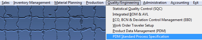
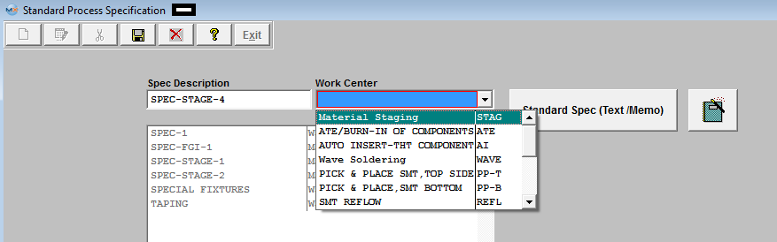
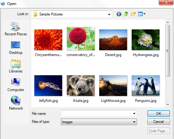
| 1.8.4.2. Edit a PDM Standard Process Specification | ||||
The following screen will be displayed:
Highlight the Specification user wants to edit. Depress the Edit button.
 User may change the Work Center, edit the Standard Spec (Text/Memo) or (Document).
Once the changes have been completed, depress the Save button to save the changes or depress the Abandon changes button to abandon the changes.
|
| 1.8.4.3. Delete a PDM Standard Process Specification | ||||
The following screen will be displayed:
Highlight the Specification user wants to delete. Depress the Delete button, enter password.
The following message will be displayed:
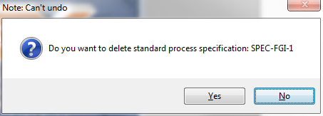 It will be defaulted to No. Depress the Yes to continue the Deleting and No to abandon without deleting the specification.
|